How to make a customized subperiosteal implant using 3D printing and almost free software
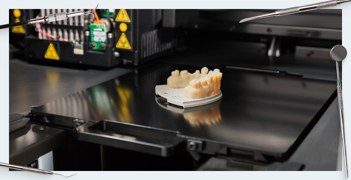
Screw implants and dentures solve most problems. However, in cases of significant bone loss, other solutions are needed, and 3D printing comes to the rescue, which can be used to produce a complex subperiosteal implant that distributes the load and allows for a complete restoration of the dentition that cannot be accomplished any other way. In this article, we will discuss a case study with an indication of the software and technology that was used to solve the patient’s problem.
What problems can a subperiosteal implant solve?
A customized subperiosteal dental implant can be an alternative treatment to sinus elevator, nerve lateralization, or zygomatic implant techniques. Such designs have been known for a long time and have been used successfully. It is now possible to produce such implants with great precision using CT scans of the patient and modern 3D printers. Digital technology makes it possible to produce complex structures quickly, which was impossible just a few years ago.
A brief description of the steps involved in making a subperiosteal implant, and the purpose of this article
Although the case described and all procedures were performed in Lithuania, which is a small European country, the study of techniques and methods will be useful for specialists all over the world. Here are the steps to go through to get a completed implant.
- Obtain the original data, specifically the patient’s CT scans.
- Select the necessary software to process the original data, correct errors and model the 3D implant. Software for design and data processing in the medical field in the USA costs tens of thousands of dollars, but here we used free or almost free programs. With their help, we got an excellent result.
- Creation of a virtual 3D model of the patient’s jaws.
- Modeling of an individual implant and preparation of a data file for printing.
- Printing a plastic model of the jaw.
- Printing the individual implant made of titanium alloy grade 5.
- Try-on and fitting of the subperiosteal implant on the model of the patient’s jaw.
The surgical procedure for implant installation and dental restoration is not described in this article, as it focuses on the modeling and error correction procedure for the manufacturing of customized implants on a 3D printer.
The objectives of this article are:
- Define a digital workflow from CT scan to printed implant.
- Elucidate variables affecting the quality of the end product,i.e., the implant.
- Determine the possibility of completing this task using freely available software.
A brief history of the invention and use of subperiosteal implants
The most common need for dental implants is in the elderly. Elderly patients are more likely to have significant bone volume loss and are also not good candidates for bone augmentation because of their reduced metabolic rate and regenerative capacity.
One solution is subperiosteal implantation, which circumvents the problem of severely resorbed bone. This type of implant was introduced by Dr. Gustav Dahl in 1937 in Switzerland. By now, with the development of directed bone regeneration, the dental community has all but forgotten about this treatment option. Even today there is a large enough group of patients for whom the method of treating adentia with the installation of subperiosteal implants is better suited than all other methods. These are patients with severely reshaved jaws or who have lost a significant amount of bone due to accidents or incidents.
In the classic version, the subperiosteal implant is manufactured in two stages. During the first operation, an impression of the jawbone is taken. A customized implant is then manufactured in the laboratory and placed during the second operation. However, two surgeries are an increased risk of complications, and the patient experiences a lot of pain and discomfort even if there are no complications.
With the advent of computed tomography and new methods of manufacturing free-form parts such as:
- stereolithography
- fused deposition modeling.
new approaches to patient care have appeared. CT scanning is no longer a purely diagnostic procedure, and the ability to quickly create jaw models and implant prototypes has made it possible to do away with only one operation for direct installation of the subperiosteal implant.
It is worth noting that this technique has made it possible to produce anatomical models and implants for other anatomical regions as well:
- parts of the skull;
- vertebrae;
- components for prosthetic joints, most often hip joints;
- surgical templates and other customized instruments and devices.
The first documented case of manufacturing a prosthetic device using 3D digital technology was a subperiosteal implant made by Dr. James R.A. in 1985. At that time, direct metal printing was not available, so CT data was used to create anatomical models of the mandible on which the implant was modeled and traditionally cast in metal.
After EOS (Krailing, Germany) introduced Direct Metal Laser Sintering (DMLS) in 1995, it became possible to produce three-dimensional objects of any complexity from metal. This opened up the possibility of fully digital manufacturing processes. That is, manufacturing prostheses without taking impressions and casting. The anatomical model of the jaw is created from a series of CT images, then a virtual model of the implant is created and transferred to the 3D printer for printing. Biocompatible metals or alloys such as CoCr (cobalt chromium) or Ti64 titanium are used for the direct printing of dental implants. The following four methods of manufacturing subperiosteal dental implants are in use today (as of 2018):
- Traditional method with bone impression and metal casting from fabricated models.
- Transitional method: CT + 3D printing of a plastic jaw model, manufacturing a melted model from ashless plastic, and casting from a metal model.
- Completely digital method. Uploading CT data, modeling the implant on a virtual jaw model, and printing on metal using DMLS or similar technology.
- Hybrid method. Optical scanning of the jaw impression (silicone or plaster model). Simulation of the implant on a virtual model of the jaw. Printing in metal using DMLS technology or similar.
Let’s analyze these methods in more detail. The classical technology is the most labor-intensive and traumatic for the patient. During the first surgery, an impression is taken with silicone material. Then the implant is modeled on a refractory model of the jaw made from the impression. Next, the implant model is manufactured from ashless material and cast in metal. The metal takes up the volume of the model and follows its shape. The finished implant is then finalized and adjusted on the jaw model. It is then placed in the patient during the second operation. The time interval between operations is 2-3 weeks.
The second method does without one operation, due to the CT data obtained in advance. Based on the CT data, a refractory model for casting the implant is manufactured, which is a duplicate of the 3D-printed model. It is assumed that the specialist has access to CT and 3D printing of arbitrary plastic molds, but does not have access to metal printing technology. The disadvantages include the large number of steps and the duplication of physical models. At each step, small inaccuracies accumulate requiring adjustment, which means there is a risk of a suboptimal fit of the implant in the patient’s jaw. The accuracy of implant manufacturing with the second method may be less precise than with the classical method.
The third method is the shortest way to the end result with high accuracy. Here, no additional 3D printing steps or model duplication are required. Most of the processes are done digitally. CT scan data is used to create a virtual model of the jaw, and the implant modeled from it is immediately transferred to metal printing.
The fourth method seems redundant and unnecessary but is sometimes used in practice because implants fabricated on a digital model do not always fit well enough due to possible inaccuracies in the digital model generated from CT scans. Therefore, in situations where the implant made by the third method does not fit the real jaw well, i.e. there are large discrepancies between the implant and the bone, the surgeon should follow the fourth method. That is, take an impression and postpone the implantation until a new implant can be fabricated using the “hybrid” method.
This article will describe the third (digital) method of manufacturing a subperiosteal implant.
Data source and software used
The original CT data were obtained from the radiology department of the Lithuanian University of Health Sciences Hospital. A Toshiba Aquilion One multislice spiral CT scanner was used for scanning. Scanning protocol:
- 0.25 mm step;
- slice thickness 0.5 mm;
- Gantry Tilt 0°
The axial slices were exposed using the FC30 convolution core. Data were anonymized using DIOCOM Anonymizer IIIa Xe (2008).
Data processing computer PC with i5-3570 3.40Hz processor, 16GB RAM, NVIDIA GeForce GT640 1GB RAM video card running under Windows 10 64-bit operating system.
Programs used in the work in the table below:
| Name and version of the software | Manufacturer’s website | License type | What the software was used for |
| Sante DICOM Viewer FREE, ver. 4.0.14 | http://www.santesoft.com/ | free | CT dataset overview |
| 3D Slicer, ver. 4.5 | http://www.slicer.org/ | open-source software, BSD style license | CT data import and volumetric visualizationBone segmentationManufacturing digital jaw models |
| Meshmixer, ver. 10.9 | http://www.meshmixer.com/ | free, Autodesk Inc. | virtual model manipulationmodeling implantbasic model repairmeasurements |
| Netfabb Private, ver. 5.2 | https://www.autodesk.com/products/netfabb/overview | commercial, Netfabb GmbH | cutting and repair of jaw modelsrepair of implant digital modelsmeasurement |
Description of the modeling workflow
Let’s analyze in more detail all the steps and problems that were encountered, as well as the methods of solving them.
CT data processing
First, the quality of CT data was assessed. It was checked whether the area of ROI images corresponded to the required parameters. Whether the number and thickness of slices were sufficient, whether there were any scan artifacts of a different nature.
The DICOM file header should also be checked to determine if the parameters used in the scan were correct. Parameters include:
- Protocol used;
- Gantry Tilt;
- Slice thickness;
- Slice step;
- Convolution kernel.
If the Gantry Tilt is greater than 0.0°, the reconstruction program may not be able to make edits that compensate for the shear distortion of the model. The beginning and end of a series of CT images often contain defective slices that have to be discarded when viewing the dataset, see illustration below.
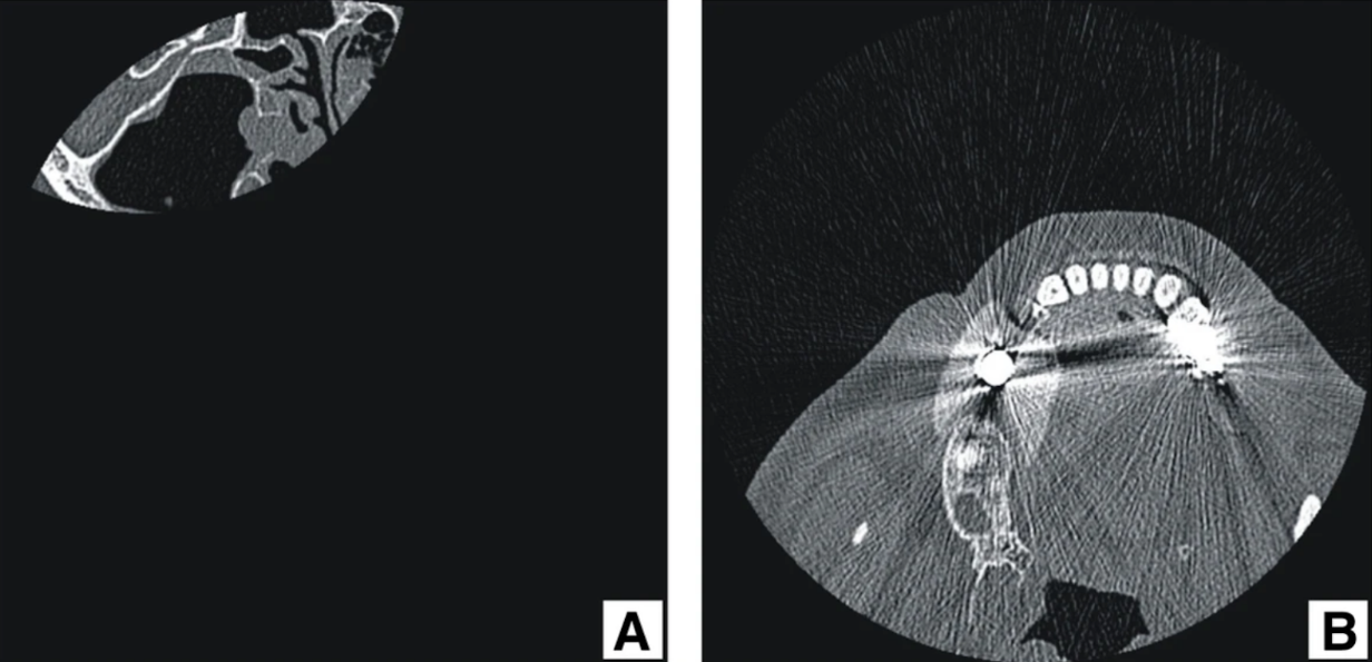
Fig 1 CT errors: a ) incomplete image; b ) x-ray scattering artifacts from metal objects in the patient’s tissues and cavities
If the CT data contains errors, such as scattering caused by metal or motion artifacts, it is necessary to determine how much these errors affect the anatomical region in which the implant will be modeled, see the illustrations below.
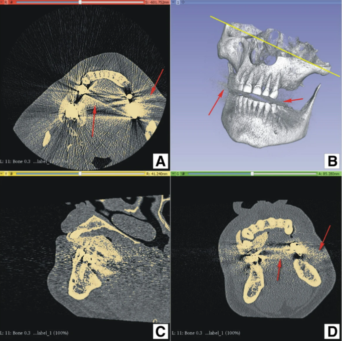
Image 2 Modeling3D Slicer user interface, four-level layout: a ) b ) d ) red arrows indicate X-ray scattering artifacts; a ) yellow line highlights the angular position of the patient during the CT scan to avoid artifacts in the left maxillary region important for modeling; a ) c ) d ) ivory indicates the threshold marker that will be used to create the model.
If distortions affect the anatomical region where the implant will be placed, a decision must be made whether to repeat the CT procedure or to take a physical impression of the bone. If the CT artifacts do not affect the area where the implant is to be installed, then it is possible to proceed to the segmentation step. The image set should also be evaluated for motion artifacts, which can only be seen in a reconstructed sagittal projection or three-dimensional volumetric imaging.
Importing CT data and creating a virtual jaw model
The Slicer 3D program was used to create a 3D model of the jaw. Bone segmentation was performed according to the online manual for this program.
A critical step is the proper selection of the threshold for the tissue of interest. The specific threshold at which the program will plot the surface is influenced by factors such as:
- the CT scanner;
- the software settings (convolution kernel);
- the volumetric framing of the CT scan;
- the bone density of the actual patient;
- the choice and actions of the operator.
The human factor in the threshold selection decision is very important, and represents the sum of anatomical knowledge and operating experience that equipment cannot yet replace.
Once the desired volume label threshold is selected, a surface model of the selected anatomy is created, see the following illustrations.
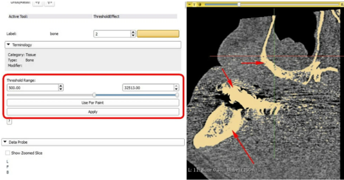
Image 3 3D Slicer user interface, thresholding tool: thresholding level selected using slider or entering numerical value (depicted by red rectangle). Bone label (standard from Slicer3D) is visualized by ivory colour in slice image (depicted by red arrows)
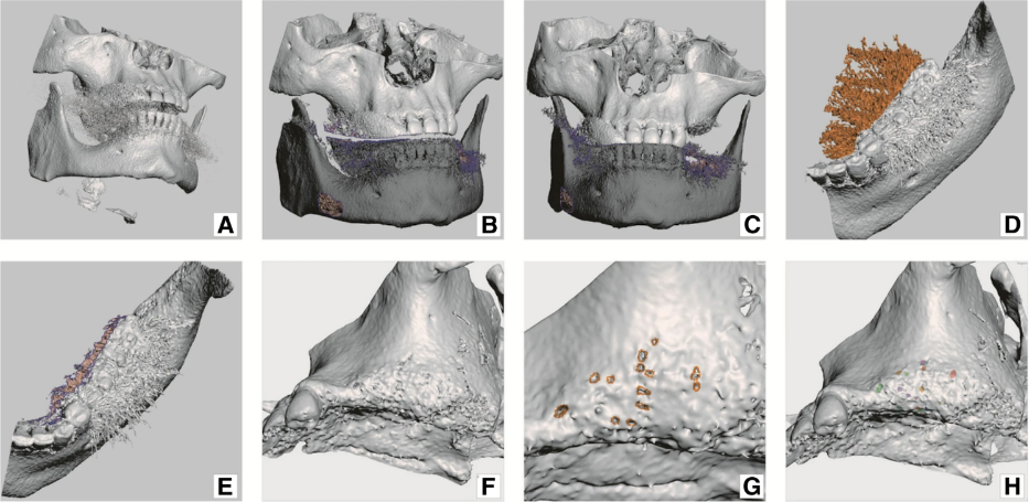
Image. 4 Model preparation: a) newly generated bone tissue 3D model (mesh); b) model – fragments of vertebrae, hyoid bone and some noise were removed; c) maxilla and mandible have put into occlusion; d) mandible trimmed down to size necessary for work; e) more noise removed from mandible; f) maxilla presenting anatomical holes (apertures); g) “healing” anatomical holes in maxilla; h) “healed” maxilla, colour patches represent former anatomical holes
The polygonal mesh was saved in .stl (STL) format because this format is compatible with all existing 3D modeling software. The STL format describes 3D objects as meshes of stitched triangles. All segmentation programs, including commercial software are prone to errors when building mesh models of anatomical structures.
The meshed structure (3D model) created by CT data processing often contains edges with a slightly shaped surface, holes, inversion triangles (pointing deep into the model), and other errors that complicate further processing steps. Human bone is a difficult structure to process because of its trabecular and cavernous structures. Therefore, it is difficult to describe with the closed surface mesh structures used by 3D modeling software. This is especially evident in the way the program tried to recreate the trabecular bone structure in frames F and G, in the illustration above.
Specialized error correction programs such as Netfabb are used for such cases. However, such correction only corrects program errors in the segmentation process, but does not correct holes in the anatomical bone structure. Fenestrations in the virtual bone model can be part of the patient’s real anatomy, or be thresholding artifacts. Anatomical holes should be corrected manually or avoided in modeling, an example is on slides G and H in the previous illustration.
Implant modeling
- Out of concern for the patient’s health, the number of mucosal perforations must be minimized. Each abutment that will hold the denture is a passage from the non-sterile environment of the oral cavity to the sterile environment of the body. Yes, a soft tissue attachment is formed around the abutment, but as we already know, the gingival cuff around the implant neck and abutment is inferior in quality and quantity of fibrin fibers compared to the soft tissue complex around a living tooth. In the long term, there is an increased possibility of bacterial invasion and inflammatory processes that weaken the contact between implant and bone. This is also observed with single implants, but the problem of weakened contact is more pronounced for subperiosteal implants, in which only 30-40% of the volume is in contact with bone tissue. The remaining surface is surrounded by soft tissue. Therefore, the possibility of bacterial invasion should be minimized by reducing the number of mucosal perforations.
- When modeling narrow spaces, gaps and concavities should be avoided, especially near the abutments. Plaque and microbiota can accumulate in such areas. It is important that the implant has the best possible contact with the periosteum, and that there are no areas where the implant interferes with the blood supply and tissue healing after installation. It is recommended to use the smallest possible amount of metal and to calculate the implant so that the masticatory load is distributed as evenly as possible.
Before modeling the implant, it is necessary to plan how the dentures will be positioned. The aesthetics and functionality of the denture should be taken into account. For this purpose, the virtual jaw models must be centered. Use the existing interdental bite as a reference point or use the X-ray markers in the removable dentures as scanning aids (slide B and C in the previous illustration).Physical models of the jaw with waxed teeth can be used for preparation,and also use a virtual tooth model in the program. This will help to determine the locations for the abutments on the future implant. See illustration below (slides B, and C)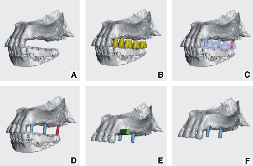
Image. 5 Model preparation continued: a) virtual jaw models in occlusion; b) virtual teeth added; c) prospective abutments have been placed in places corresponding to future teeth; d) future abutments – sky blue abutments belong to subperiosteal implant and red one belongs to planned screw type implant; e) a cut-off tool placed in the area of tooth 24 (FDI), where abutment was planned to bury deeper into the bone; f) maxilla with cut-off and placed abutments
Also, consider the lateral movements of the jaw. Analyze the anatomical and mechanical fixation of the implant. When modeling the implant, consider the presence and position of the abutments relative to the remaining teeth or other implants in the patient’s mouth, as well as the position relative to the antagonist dentition. The difficulty of modeling the dentition in this case is that it is necessary to form a completely new dentition, and not to make a mirror image of the relatively existing one. Creating an anatomically correct bite is a complex job that requires the right digital tools. Among all the programs for dental prosthetics, it was very difficult to find a suitable package. To a first approximation, software for modeling partial removable dentures seemed promising because of the similarity between the subperiosteal implants and the framework of a partial removable denture. However, testing of several packages showed that this path was of little use because these programs do not allow modification of the jaw models, or require extensive customization to be useful.
- The 3D model of the subperiosteal implant in this case was created using the Meshmixer program, which allows working with a mesh brush. Modeling was performed on two digital copies of the jaw. On the first copy, the convex part of the implant itself was created from a virtual material that replaces real wax or clay, with the help of which the dental technicians created a model of the implant on a refractory model of the jaw. The second copy was used to model the inside of the implant (adjacent to the bone). The full 3D model was created by adding andsubtracting the volumes of the inner and outer parts of the implant. Let’s analyze this point in more detail.
Details of implant modeling and correction of inaccuracies before printing
When creating the virtual implant model, the digital images of the maxilla and mandible should be centered so that they are positioned as they would be in reality (image 4 slides B, and C). This will help to plan the placement of the abutments. In addition, the virtual teeth should be placed on the digital model – this will also help to plan the positioning of the abutments and the future occlusion.
The placement of the abutments depends on the current bone configuration and the future prosthetic plan. In addition to the anatomical shape of the bone, the quality of the bone should be taken into account. The bearing and retention elements should only be planned where the cortical layer is at least 0.8 mm thick. In our clinical case, the retention elements were placed at the specified locations. Then all the listed elements were combined on one copy of the jaw using a Boolean addition operation. See Image 6, slides B, and C: and image 7, slides A, and D.
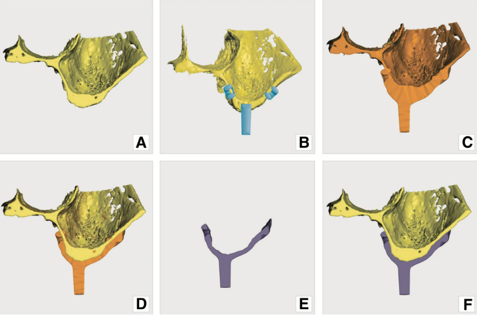
Image. 6 Modeling principle: a) original model of the jaw; b) pre-made structures (loops and abutments) added on to virtual model; c) pre-made structures and modelled (bulked) implant merged with original model; d) the 2nd copy of original model (yellow) recalled and matched with model onto which implant was modelled (orange); e) implant – result of Boolean operation, subtraction of yellow model form orange model; f) implant (resultant) model superimposed on the original jaw model. (Screenshots from Meshmixer program)
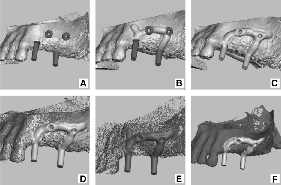
Image. 7 Modeling in Meshmixer program: a) pre-made structures (loops and abutments) added on to original jaw model; b) implant modeling (bulking) by sculpt tool; c) pre-made structures and modelled (bulked) implant merged with original model; d) the 2nd copy of original model (dark grey) recalled and matched with model onto which implant was modelled (light grey); e) implant – result of Boolean operation (with lots of unwanted shells), f) implant (resultant) model superimposed on the original jaw model
In the next step, the connecting elements that unite the abutments and retention elements are modeled. This is done using the different brushes of the “SCULPT” tool in the Meshmixer program. See image 7, slides B and C. The abutments and retention (retention) loops are connected by belts that are formed by the virtual brush and can be seen in the illustration above.
The thickness of the connecting elements of the subperiosteal implant is usually 1.5-18 mm, and this value is empirical. When creating the digital model, the thickness of these elements is increased by 0.2-0.3 mm to allow for machining of the physical model before implant installation. Surface treatment is always necessary because of the 3D printing process (DMLS), which results in a rough and oxidized surface of the printed parts. After printing and separation from the substrate, the printed part requires surface treatment, so additional thickness is included to reduce it to normal values after treatment.
How Boolean subtraction works when modeling an individual implant
Without this logical operation, it would not be possible to create the final product using the above software. Two virtual models are used as original data. The first is an anatomical model of the patient’s jaw, which was created using CT data. The second model is the same jaw model with the structure of the future implant protruding from it. The procedure of Boolean subtraction consists of the volume of the first model being subtracted from the second model, the remaining structure is the model of the implant we need, see images 6 and7.
Correcting inaccuracies and removing artifacts created during the modeling process
The virtual implant model almost always contains small remaining artifacts in the form of small snowflakes left after the Boolean operation. These artifacts are the result of inconsistencies accumulated during the whole chain of manipulations with the digital model. To understand what we are talking about look at slide D in image 7, and slide B in image 8. Such structures have to be removed manually and corrected with the help of programs:
- Meshmixer;
- NetFabb.
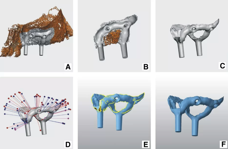
Image. 7 Modeling in Meshmixer program: a) pre-made structures (loops and abutments) added on to original jaw model; b) implant modeling (bulking) by sculpt tool; c) pre-made structures and modelled (bulked) implant merged with original model; d) the 2nd copy of original model (dark grey) recalled and matched with model onto which implant was modelled (light grey); e) implant – result of Boolean operation (with lots of unwanted shells), f) implant (resultant) model superimposed on the original jaw model
Error correction and artifact removal are some of the most important steps in the modeling process. First, inaccuracies and defects are removed on the jaw model, and at the final stage, cleaning and “repairing” the surface of the implant itself is important.
In general, correction and restoration of the model are required before and after each subtraction or addition operation. The software can’t process the data correctly if the polygonal meshes contain errors.
Final checking and error correction are especially important. Professionals need to be sure that the printed implant will fit, and fit in the correct position in the patient’s mouth.
Checking and correcting errors on a virtual model is usually a multi-step process that requires attention and effort. Perhaps data processing systems based on artificial intelligence may soon help to perform modeling faster and with fewer corrections. To date, the following programs for error correction of digital models formed from polygonal meshes are freely available:
- Netfabb Basic (full list of fixed bugs, automated scripts).
- MeshLab (no automated scripts, requires manual selection for each type of error to be fixed).
- 3Data Expert lite (limited repair options in the free version).
- GOM Inspect V8 SR1 (ability to fix some bugs).
- Meshmixer (automatic bug fixing, several fixing options, not enough even for the internal needs of the program).
- Netfabb contains pre-compiled repair scripts for fixing bugs of different levels of complexity. This option makes mesh recovery operations easier for the user. Netfabb Private provides three pre-compiled grid recovery scripts. These scripts have sufficient completeness to detect and correct errors. The table below lists the options for the Netfabb program’s pre-compiled recovery scripts.
| Simple repair | Default repair | Extended repair |
| close trivial holes | lose trivial holes | close trivial holes |
| close all holes | close all holes | close all holes |
| fix flipped triangles | fix flipped triangles | fix flipped triangles |
| stitch triangles | stitch triangles | |
| remove double triangles | remove double triangles | |
| remove tiny shells | remove tiny shells | |
| remove degenerated faces | remove degenerated faces wrap part surfaces |
In this case, the script was used at all stages where a repair was needed: Default repair, see image 8, slides D and E.
Printing of the subperiosteal implant
After the digital processing was completed, STL files with the implant and the model of the jaw on which the implant will be placed were generated, see image 9 slides A, B, and C. The finished files were sent to a 3D printing house with the appropriate equipment (UAB Orthobaltic, Lithuania).
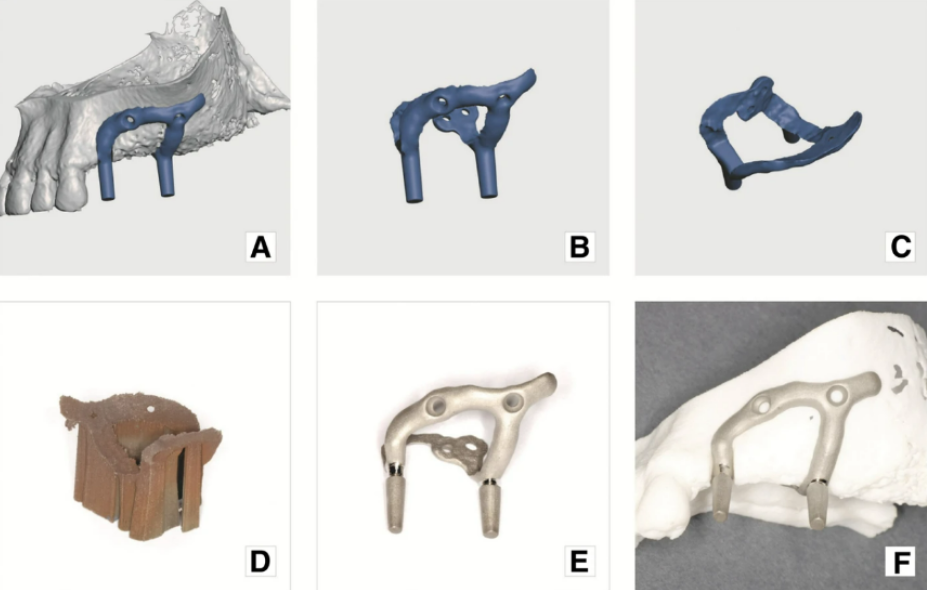
Image. 9 Final result: a) implant digital model superimposed on the jaw virtual model; b) and c) implant digital model in different projections; d) implant with printing supports, immediately after production; e) implant with supports removed and mechanical grinding and polishing completed; f) subperiosteal implant on the plastic model of maxilla
The task of the typography company is to print two products:
- A polyamide model of the patient’s jaw, for checking and fitting the implant before surgery. The printing was done on an ESO P 396 printer in 60 µm layers.
- The implant was made of Ti64 titanium alloy using DMLS technology, in 100 µm layers, on an EOS printer EOSINT M 280. The implant was printed and then annealed in an argon environment. Any support elements that remained after printing were removed, and further processing of the implant was performed by the dental technician.
The inner and outer surface of the implant was checked for voids and swellings. The detected defects were removed with an abrasive tool. The accuracy of the fit was checked on a plastic model of the jaw.
Подробное описание процесса обработки импланта выходит за рамки этой статьи, поэтому отметим только самое важное:
- the final profile of the implant was achieved by machining with carbide drills;
- after the drills, the surface was blasted with ≈150 µm aluminum oxide particles at a pressure of 5 bar, see image 9 slides E, and F.
Analysis of the results received
- The patient’s CT data were successfully converted into a digital mesh (.stl) model of the maxilla using the open-source program Slicer 3D.
- Error correction and design were performed using the freely available programs Netfabb and Meshmixer from Autodesk Inc
- This article describes the process of fast and high-quality modeling of a subperiosteal implant using tools available anywhere in the world.
- The subperiosteal implant was successfully printed from Ti64 titanium alloy using DMLS 3D printing technology.
- Other steps, such as final surface treatment, surgical, and prosthetic steps, are beyond the scope of this article. The clinical results of the use of 3D-printed subperiosteal implants will be presented in separate publications.
- Legal Background: Patient-specific (customized) implants do not require CE certification. According to the Medical Devices Directive (MDD) 93/42/EEC, “a custom-made medical device is any device specially manufactured in accordance with the written prescription of a qualified medical practitioner, which, under his responsibility, imparts specific design characteristics and is intended for the exclusive use of a specific patient.” Patient-specific (customized) implants must comply with the relevant basic requirements set out in the MDD, if applicable, to ensure their safety. Legislation may vary from country to country, but in most cases, customized implants do not require additional certification.
- However, it is worth remembering that software used to model individual medical devices is also considered a medical device. Computer programs that process patient data are generally considered Class IIb medical devices. In the European Union, they must be CE-certified. None of the programs used in this publication are CE-certified. To the authors’ knowledge (as of 2019-2004), there is only one CE-certified medical device design software package. This is 3-Matic Medical by Materialise. However, its cost is prohibitive for small companies.
Conclusions
Customized dental implants are a sought-after product that occupies a significant niche in dental practice. This article proves that it is possible to produce a medical device (subperiosteal implant) of adequate quality without the use of expensive software. The possibilities of free or inexpensive software for modeling and correcting 3D objects were demonstrated. A dental implant of adequate quality was designed and fabricated based on the CT data.
However, medical device developers need to consider many factors that affect the quality of modeling and the accuracy of manufacturing the final product:
- CT scan data quality.
- Segmentation software algorithms and settings.
- Modeling software output quality.
- Error repair software algorithms.
This means there are prospects and benefits for both patients and dentists in developing specialized software for the simulation and correction of virtual models of medical implants.
Source
BMC Part of Springer Nature (3D Printing in Medicine) – A digital workflow for modeling of custom dental implants.

