How to align Digital Analog to 3D printed model of dental implant | CAD CAM Digital Planning
Hello everyone and welcome back to Uniqa Dental Show where we discuss interesting cases and new procedures in the field of dentistry. Today we will show you a unique solution to one of the most common problems in digital dentistry. Today with Dr. Yaniv we will go through this.
What problem did the patient come to us with
What we’re going to talk about today is not about this case. This case is just an example of when and where we would use it. But in this case, we can show that when you’re using CAD/CAM, sometimes you need to have a good and accurate model. For example, if you want to make a PFM restoration, porcelain fused to metal. So, the technician that designs the porcelain needs to have a metal to design to be based on, and you need to have good digital analogs and you need the analogs to fit correctly to the model that you print in. So, from our experience, what we saw in different companies, you have a good digital analog, but every technician uses different material, different printers, and you have some deviation between the analogs and the models themselves.
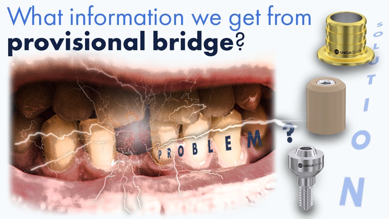
So, if one technician uses one company’s analogs with some material printer, the analog can fit correctly, or it can be loose or doesn’t fit at all. And there is no solution to solve this problem. So, right now in here, we’re going to show a way on how we’re solving this problem with our special libraries. In this case, what we see is, we see on the upper jaw, temporary restoration. From PMMA, you can see problematic teeth on both sides.

Temporary prosthesis made of PMMA plastic – the patient’s living teeth affected by caries are visible on the sidesYou know that it’s temporary. You know you can see even the caries from the bridge. These teeth, we need to extract.

The removed bridge and the remains of teeth that were also subject to removal
Now, if we move fast-forward, we take off the bridge and we extract the teeth. Now at this moment, we need to have some implantations. We need to place implants. Some of the implants will go in their anterior region. Some of the implants in the posterior. We place the implants. We make sutures, and we wait until we can choose what type of multi-units we want to use and take impressions.

Installed implants at the healing stage
We made impressions. Now is the problematic part, because now I need to have a working model. Now I need to adjust the upper lip, the lower jaw, and connect all the parts of this case.
For this case, a working physical model is needed, especially if a PFM prosthesis is intended. In zirconia, for example, if you’re making a crown or two crowns or small bridges, in many cases, you don’t need a working model at all. Because if you have monolithic zirconia, you have the working model in your computer.
You don’t need to have a working model because you don’t need to put in ceramics. You can just glaze it, color it a little bit. It doesn’t have a thickness at all. So, you can finish the case without a working model. In cases when you need to add ceramics, in cases when you have PFM, in cases when you need to check or when you need to move things, or you need to visualize, you need to have a real-life working model. And when you’re using CAD/CAM. It’s a problem to have a working model because everything is digital.
You need to take all the digital information and make it real. You need to print the working model. And the working model is made from plastic. So, you need to have digital analogs that will be inserted to the working model. The digital analogs need to fit well, or else the bridge that you will design originally on the digital working model wouldn’t fit on the model, on the working model that you have in your hand. So, in this case, we can see a scan.

Digital model using scan abutments (on the upper jaw) and a bridge prosthesis (on the lower jaw)
We can see a scan of the six upper implants. It’s a case of like all six, you can call it. We can see the scan abutments. The impression was taken on a multi-unit level, it’s scan abutments for multi-unit level. And what we want to do now is we want to, from this part, have a working model and be able to make a PFM.
In this case, the doctor wants to have a PFM in the end. This is the end result. In the end result, you can see that we have a PFM made from two parts. We have the base with the gingiva. You have all the screw channels in the base, and you have different crowns.

Metal-ceramic prosthesis – base with screw channels and porcelain crowns
There will be an alloy of porcelain crowns with metal. And it was on a working model. For this type of work, you must have a good working model because you take out and put back in a lot of times, the base and the crown, so you’ll play with it a lot. So, your working model needs to be good, needs to be with high standards, high quality. Now the problem is getting these types of working models. You can see here the doctor designed the working model from two parts. You have a gingiva that was printed separately, it will be printed separately.

Metal-ceramic prosthesis – base with screw channels and porcelain crowns

Upper jaw model with implant analogs

Gingiva Model with Implant Analogs
And you have the base of the working model. In the base of the working model, it’s made from hard plastic. Hard plastic can be printed a little bit differently with different types of printers and different types of materials. So, in this case, if you use some kind of printer or other materials, you might get different results.
You can get different results depending on the material, depending on the shrinkage factor of the material, because it’s a big model.
The shrinkage factor will be quite large in this case. You have a large height of the model. The model itself is very big. So, now what you need to do is to calibrate the place of the analog, according to the model, to the printer, and to the material that you’re using. What we recommend is every time you change the printer, or every time you change the material from one material to another, make a calibration.
How to improve the accuracy of manufacturing a physical model
When you download our library, what you have is in the folder of the library, you’ll have a space of scaling.

3D Printer Calibration Library
Space of scaling is what we call different types of spacers around the nominal spacer. For example, the normal spacer, we called 1.0. You can have a smaller spacer or a bigger space depending on the nominal one that we chose. In addition to these spacers, you have a calibration jig.

Calibration fixture
It’s a block of four calibrations that has different types of holes that can demonstrate different types of spacers. It looks something like this. You can see here what type of analogs you’re using. If you’re using analogs for internal hex implants, this jig is what you need. You have five different holes with different kinds of spacers, and you have the name of the spacer of the corresponding hole.
So, you print this jig, you take the analog that you have, and you just try to insert it to each one of these holes. The hole that it fits best in, you just take the files from this spacer. You move them to the main library, the main folder of the library. And you’ll use this spacer, every time you change it from one material to another, or changing to a different printer or making a large change in the printing technique. You probably need to calibrate again, to have the best results you can get. And this way you can get, first of all, you can print the gingiva, you can print the temporary model. You can print the model of the temporary bridge. You can print the model itself. Everything will fit just as it’s supposed to fit in the mouth.
Thanks to the calibration, because the spacer fits, the analog fits best in the model. And each time something doesn’t fit, you have more and more deviance from the original positioning in the mouth. Every time you take impressions, you print something, you make a model of something, you lose the accuracy that you originally had. So, this way we try to maintain the most accurate result.
Every step needs to be calibrated. Here, if you calibrate, you’ll get a good fit between the analog and the model and the bridge that you design will be made on the original models that you scanned in the patient’s mouth.

Working model printed on a 3D printer
You don’t scan on the working model at all. It’s not recommended at any time.
This is a truly innovative solution to make analog more accurate.
And it’s a really easy one. You just print this box and physically insert it inside.
You don’t need to change anything in the printer. You do everything in the library in exocad. It’s all available. You just switch the files and you have everything for this printer with this material. You don’t need to contact anyone. You don’t need to do anything.
Thank you for being here today. We hope you enjoyed it. We will keep posting new, innovative solutions on our YouTube page, which I invite you to like, subscribe, share, follow, and send us your interesting cases.