An Introduction to Implantology: Dental Doctors’ Manual
Contents
In this article, we will discuss the protocol for dental implant placement using specific clinical cases. We will understand the peculiarities of the preparation for and planning of the surgery. We will look at how bone density affects the choice of drill diameters and the shape of the cavity; and how to perform complex implant placement at the same time as an open sinus lift. This article is intended for young professionals and experienced dentists who do not often practice surgical procedures.
Preparing and planning the surgery
Even in the case of a simple single implant placement, a CT scan of both jaws and several targeted X-rays of the areas to be worked on are mandatory.

Example of a targeted X-ray of an already placed implant with crown

Example of an orthopantomogram
Flat images, for all their advantages, do not show the complete picture. Hence, the “gold standard” is a full examination with cone beam computed tomography (CBCT), where all teeth are seen from different angles. Foreshortening can dramatically change the understanding of a situation, as evidenced by the though not medical, but informative photos below.

Getting a 3D model of a jaw has become much easier with modern software today. A CT scan gives much more information than any targeted X-ray. The example below shows well how informative a CT scan can be.

CT scan of the patient’s dental condition
We will need four scheduling windows for the surgery we are evaluating:
- Bone condition,
- Bone ridge thickness and shape;
- Distance to neighboring and antagonist teeth;
- Root location of neighboring teeth; and
- Distance to the mandibular nerve.

Coronal slice – here you can see the bone density, width, and shape of the bone ridge

Sagittal slice – here you can see the neighboring teeth and antagonist teeth

Axial slice – here you can see the location of the mandibular nerve

3D visualization provides a general understanding of the surgical plan
This enables you to choose the length and diameter of the future implant. We will not focus on the peculiarities of specific programs for working with CT scans, but they all enable you to view all slices oriented on the axes, measure all the necessary distances, and even draw the location of the mandibular nerve. This is very important because you must leave a safety zone of 2-3 mm, and if there is 11 mm from the alveolar ridge to the mandibular nerve, you cannot place a 10 mm implant in this spot.
It is equally important to see the location of the roots of neighboring teeth. If a tooth was lost a long time ago, it is common for the orthodontist to need to spread the teeth near the defect. However, after successful displacement of the crowns of the neighboring teeth, the bending of their roots may enter the area of the intended implant placement. Therefore, it is critical to measure both the intercoronal and interroot distance between neighboring teeth.
Moreover, all visualization programs have libraries of dental systems, or at least there is an option to load the library from the required manufacturer. Uniqa Dental, like most other manufacturers, provides its customers with access to its library.
In the next step of planning the surgery, we select the right size implant from the library and customize the position of the implant relative to our defect. See the images below. The implant should be placed as close as possible to the axis of the future crown. The location of the future crown helps to determine the tooth antagonist.

Plan of implant placement in the patient’s mandible
The distance to the tooth antagonist is also important to consider. In this clinical case, the plan is to place the implant below the bone level so that there is enough space to create a crown with an optimal eruption profile. It is equally important to position the implant so that there is a sufficient bone wall of at least 2 mm thickness on both the lingual and vestibular sides.
Anesthesia based on human jaw innervation
Let’s move on to the surgical phase. We also omit the patient’s clinical presentation as we review the surgical protocol for patients with an uncomplicated medical history. Briefly recall that it is necessary to pay special attention to patients with hypertension and diabetes mellitus, and of course to find out if the patient is not allergic to drugs for anesthesia.
Even a single implantation is a fairly complex surgical procedure, so both infiltration and conduction anesthesia are recommended.

Scheme of innervation of the jaws from the trigeminal nerve
Only such a powerful blockage will allow the patient to be free from discomfort during surgery. How to do painless injections is described in a separate article, so we will not dwell on it here.
Implant placement
With the preliminaries completed, we move on to surgery. The 15 series blades, most commonly 15C, are used for gingival dissection.

Soft tissue scalpels in dentistry
The incision is made by holding the scalpel perpendicular to the bone. The start of the incision should be at a point farther away from you. Plunge the scalpel in, and make the incision towards yourself. Then make incisions on the lingual and vestibular sides to expose the alveolar ridge.

Recommended incision pattern for the placement of two implants
Flap detachment
Once an incision has been made, the mucosa-periosteal bone flap must be peeled away. There is a very important point here: do not delaminate the soft tissues. If you separate the mucosa from the periosteal tissue, you get a lot of swelling and healing problems.

Flap detachment to access the alveolar ridge
After the incision, fold back the edge of the flap with a sickle-shaped ironer and further separate the flap from the bone with a sharp raspatory.

Exposed bone in the area of implant placement
Let’s see what this process looks like in reality, taking the clinical case of single implantation as an example.

Initial clinical situation before implant placement
Hold the scalpel perpendicular to the alveolar ridge. Plunge it until it contacts the bone and make an incision without preserving the papillae, from the equator of one tooth to the equator of the other. The cut is made along the top of the ridge. As the photo shows, the cut is made towards you.

How to make a soft tissue incision for dental implant placement
Next, fold back the edges of the flap with a sickle-shaped ironer. As the photo shows, access to the alveolar ridge is open. It can be seen that the width is quite good, and the bone tissues are well vascularized. This is an encouraging prognosis.

How to detach a flap to access the alveolar ridge
IMPORTANT EXCEPTION! Flap detachment in the aesthetic area has its peculiarities. In no case should the incision be made over the dental-gingival zeniths of neighboring teeth, nor the gingival papillae, or they simply will not form around the crown. The incision should be made as shown in the first or second diagram below.

Recommended soft tissue incision zone in the area of the anterior teeth – option 1

Recommended soft tissue incision zone in the area of the anterior teeth – option 2
Another challenging location in terms of soft tissue work is the soft tissue detachment to access the lateral wall for subantral augmentation (sinus lift) surgery. Under no circumstances should the incisions be too high. We work only within the confines of the attached keratinized gingiva, never into the area of mobile mucosa. In cases where the keratinized attached gingiva is reduced and not contoured, note the diagram showing the location of the blood vessels, specifically the arteria maxillaris. The diagram shows an unacceptable incision height. If the incisions are made too high, the artery may be severed and bleed profusely.

Unacceptable height of gingival incisions
The incision should be made along the intra-furrow line in front of the front two or even three teeth.
Preparation of the implant bed
Let’s consider the case of placing two implants side by side as more complex and useful for learning. When the access to the cortical layer of the bone is opened, two basic parameters must be determined to ensure a favorable prognosis of the surgery.
- The positioning point where we will put the drill, and
- The convergence angle so that both implants point toward the center of the fissure of the future crown. The positioning of the implants relative to each other is also important.
There are two options for this clinical case:
- Manufacturing a navigational (surgical) template that will set the exact position for the implant bed, both in terms of positioning point and angle. However, using a navigation template is not always convenient, or justified; or
- Preparation of the bed with position verification with pins. This option is suitable for both experienced surgeons and beginners. We will go into it in more detail.
In the diagram below, we can see that the last tooth is the fifth tooth. Once again, we remind you of the importance of preparation for implantation. Very often, the root of the fifth tooth is bent towards the sixth tooth, and there is a chance that it may get caught when drilling the implant bed.
A Lindemann drill is used as the pilot drill in this diagram, but other options are possible. For example, passing through the cortical layer with a spherical bur, and then passing through with a 2 mm pilot drill.
In this article, we discuss a clinical case with a specific protocol option, but it is not suitable for all cases. To learn more about the selection of drill diameters, and the depth of each diameter depending on the bone type from D1 to D4, please see this article in our blog Dental implant placement protocols by Uniqa Dental. In short, the lower the bone density, the smaller the diameter of the last drill relative to the implant diameter. In soft bone, the implant is screwed into the bone by its coils, otherwise, good primary stability cannot be achieved.
In our example, two implants with a diameter of 4 mm and a length of 10 mm are planned. Given the distance from the bone ridge to the antagonist tooth, we need to place the implants 0.5-1 mm below the level of the marginal bone.

First penetration with the Lindemann drill to the desired depth
To know that the drill bit has already gone to the correct depth, it is marked with a yellow strip with a width of 2 mm. It starts at the 10 mm mark, so you need to go a little deeper to get about 1 mm of the yellow part of the drill bit in the hole as shown in the diagram below.

Bone penetration to a depth of 11 mm according to drill marking
After the pass in the position of the first implant with the pilot drill, we make the same pass in the position of the second implant.

Primary passage for the second implant bed
We then insert the pins into the holes to see if the holes are parallel and properly aligned with the tooth row. If there are any errors, they can be compensated for with larger-diameter drills.

Drill through the hole with a 2.6 mm drill bit without removing the parallelism pin from the second hole
Leave the pin in one of the holes, take the drill bit of the next diameter of 2.6 mm, and widen the first hole. If there are any inaccuracies, correct the drilling angle by referring to the pin.
Then, if we are satisfied with everything, we take the next drill bit with a diameter of 3.6 mm and widen the hole to its full depth. Repeat the procedure with a 4.0 mm drill bit.

Dilatation of the implant hole with a 4.0 mm drill bit
If we had an upper jaw, we would stop at this point because the bone density is always less there. In this case, we have a lower jaw and fairly dense bone with a strong cortical plate. Therefore, it is necessary to widen the mouth of the bed with a larger diameter drill or, as in this case, with a cortical milling cutter.


Widening of the implant bed for normal tapered implant placement
How to place a dental implant
After that we place the implant, first mechanically at a low speed of 30-50 rpm, seating the implant to the level of the bone.

Prepared implant bed

Mechanical insertion of the implant into the hole
Next, we use a torque wrench to manually push the implant 0.5-1 mm below the bone level. The first implant has been successfully placed.

Subcrestal implant placement
Next, we insert the parallelism pin into the already installed implant and work with the second bed according to the same principle. See the illustrations below.


Preparing the bed and placing the second implant guided by the pin placed in the first implant
IMPORTANT NOTE! If the primary stability at placement was 10-15 N*cm, a cover is placed in such implants, and the soft tissues are sutured over them. The implants are left in this condition for at least 3 months until the osseointegration process is complete.
If primary stability in the range of 30-40 N*cm is achieved, gingiva formers can be placed and even a temporary restoration can be placed immediately, if necessary. Only temporary crowns are removed from the full bite to reduce the load on the implants until full integration.


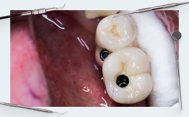
Placement of gingival formers and suturing of the flap along the contour
Gingival gormer installation stage
If the fabrication of the denture is to be done by a prosthodontist, the placement of the gum shaper is the final step in the surgical portion of the work. To form a good gum cuff, you also have to work hard. It is extremely rare for a patient to come in with a good gingival biotype, as in the image below, and it is easy to form a cavity for a future restoration.
 Biotype")
Placement of gingival shapers in a patient with a thick (fortunate) biotype
The patient in the photo above originally had covers placed in the implants. Once the osseointegration process is complete, longitudinal incisions are simply made and gingival shapers are placed. Stitches were only needed in the most difficult areas.
It is important to understand the goal and result after the gingival shaper is removed. The images below show well-formed bowls with elastic and stable gingiva. Such work is good enough to hand over to an orthopedist. If you do the full cycle of treatment yourself, it will be easier to make a restoration that the patient will be satisfied with.

Gingival formers and gingival cavities are prepared for placing restorations in the chewing section

Well-formed gingiva with pronounced papillae in the aesthetic zone is ready for crown placement
If the patient has a thin biotype, and the volume of attached keratinized gingiva is insufficient, a subepithelial connective tissue graft should be added. It is essentially a strip of epithelium-purified connective tissue. The source of connective tissue for grafting is the palate or tuberosity of the maxilla. This surgery is described in our article ”One-stage implantation with and without immediate loading”.
Placement of gingival formers – clinical case studies as an example
Let’s dissect an example of a patient with a good layer of attached keratinized gingiva. For the sake of clarity, let’s first break down the situation with the upper jaw. The patient had six implants placed on the maxilla, the implants were covered with caps, and the soft tissues were sutured.

Orthopantomogram with implant placement
The patient has good soft tissue condition and massive and thick attached keratinized gingiva. However, this clinical case can’t be called easy, as you will see.

Initial condition of the patient’s jaw
After anesthesia, we make longitudinal incisions in the places where the implants are placed according to the images. See the images below.

Finished cuts and gaining access to the cover
Slide the gingiva apically to gain access to the cover, and then remove the cover.

Screwdriver for removing covers from the implant
We install the gingiva shaper, as you can see in the picture below, in this biotype the gingiva immediately tightly compresses the shaper, and no further manipulation is needed.

Installed gingival shaper tightly surrounded by soft tissues
Unfortunately, we aren’t always so lucky. At one point, bone tissue has grown in and covered part of the implant and the cover. This problem can, however, be solved quite easily.

Bone tissue covers part of the implant and cover
You need to make the incision a little wider, take a dental bur and gently remove the bone tissue along the contour of the implant.

Bone removal to release the implant interface and cover
The work should result in a small well around the implant.

Open access to the implant cover
Remove the cover and install the gingival shaper. Since the cut in this case is slightly longer than the previous ones, sew up the edges of the cut.

Removal of the implant cover

Placement of a gingival shaper and suturing of the incision
Ultimately, the work takes the following form.

Finished work on the installation of the gingival shaper
There are times when there is excessive soft tissue tension. In such cases, it is recommended to make two small incisions on the vestibular side, not full incisions, but light incisions to loosen the tension of the tissues and to install the gingival shaper without problems.
Clinical examples of delayed protocol implant placement
We have already used some of the pictures earlier in this article, but now we will break down the steps in full.
The first example is a 42-year-old female patient with a 46th tooth extracted about a year ago. The patient has an uncomplicated medical history.

Image of the bone condition before implantation at the position of the 46th tooth
Examine the condition of the bone ridge and soft tissues, and measure the distance to the antagonist tooth. Select the implant parameters. An implant with a diameter of 4 mm and a length of 10 mm is planned. After completing the preparatory work, proceed to the surgery.

Soft tissue incision for subsequent flap detachment
The scalpel is held perpendicular to the bone ridge; the cut is made towards you from the equator to the equator of the neighboring teeth.
Next, detach the flap. This completes the preparation for drilling the bone.

Open bone ridge for implant placement
A Lindemann drill with a diameter of 2.2 mm was used as the pilot drill. Plunge to the full depth of the future hole, then widen the hole with a 2.6 mm drill bit.

Start drilling the implant hole with the Lindemann drill
Next, use a 3.3 mm diameter drill bit.

Expanding the implant bed with a 3.3 mm drill bit
The next drill diameter is 3.8 mm, remember that we need to install an implant with a diameter of 4 mm. This hole diameter is sufficient for this type of bone.

Expansion of the implant bed with a 3.8 mm drill
Take the implant and insert it into the bed mechanically first, and then tighten it manually with a torque wrench.

The implant is ready for placement

Adjusting the implant manually with a torque wrench to the desired position

The implant is placed subcrestally
Since this is the masticatory area, and the torque with which the implant was placed is less than 25 N*cm, place a cover in the implant and suture the soft tissue.

Cover inserted in the implant

Soft tissue sutures over the placed implant
If we look at the control image, we can see that:
- The roots of neighboring teeth are not damaged;
- The mandibular nerve is intact; and
- The implant axis is aligned with the center of the fissure of the future crown.

Control image of the placed implant
This means that this implant placement work has been done correctly.
Let’s look at the following clinical case, here we discuss delayed implant placement in the area of 36 and 37 teeth in the same patient, but on the opposite side.

Image of the initial state of the mandibular bone and the location of the antagonist teeth
After conduction and infiltration anesthesia, make a longitudinal incision along the apex of the ridge.

Image of the initial soft tissue condition before the implant placement surgery
Once again, you are reminded that the cut is always made towards you starting from the point farthest away from you.

Soft tissue incision before implant placement
Pull the soft tissue apart and detach the flap with a raspatory.

Flap detachment from the bone before implant placement
Drilling is done according to the same principle, starting with a 2.2 mm diameter Lindemann drill, and then a 2.6 mm diameter drill. We go through both implant insertion points with these diameters.

Drilling with a 2.2 mm diameter Lindemann drill

Expanding the hole with a 2.6 mm drill bit
After that, place pins in the holes to check thetheir angle in relation to each other, and in relation to the antagonist teeth.

Parallelism pins show a violation of the parallelism of the holes
The result shows that the pins are directed towards each other, which means that there is a defect that needs to be eliminated with larger diameter drills.

Widening of the hole with 3.3 and 3.8 mm drills with simultaneous correction of the angle defect
Operate to widen and correct the deviations on both holes. Place the implant in the first and second holes according to the principle described earlier. Both implants are first screwed in mechanically and then brought into position manually.

Preparing the implant for mechanical insertion

Adjusting the implant to the desired seating depth with a torque wrench
Once the implants are in place, reinsert the pins and see that they are now parallel and that the axes are aligned with the tooth row.

Control check of the parallelism of the implants
After checking, place covers in the implants and suture the soft tissues until the osseointegration process is complete.
The control x-ray shows that:
- The implants are placed parallel to each other;
- The central axes extend into the center of the fissure of the future crowns;
- The implants are well positioned in relation to the teeth antagonist;
- The roots of neighboring teeth are not damaged; and
- The mandibular nerve is not injured.
Which means the work is a success.

Control image after implant placement in tooth positions 36 and 37
Implant placement with simultaneous open sinus lift
The next example is more complex work, as are almost all manipulations involving the upper jaw. The clinical case is further complicated by the fact that it was performed during orthodontic treatment. See the images below.

Initial situation patient with braces
The patient received implants in all four quadrants, but we will detail only one where there was an indication for a sinus lift, namely in the area of tooth 26. See the image below.

Orthopantomogram of the initial clinical picture
To avoid gingival recession, the incision technique for flap detachment is markedly different. The incision has a trapezoidal shape.


Incision to preserve gingival volume after implant placement and open sinus lift surgery
Detach the flap and remove the cortical layer with a disposable scraper to gain access to the Schneiderian membrane. When so, collect the bone shavings for use later as bone material for the sinus lift.

Flap detachment for bone access

Removal of the cortical layer to access the Schneiderian membrane with a disposable scraper
Using a special diamond drill, shape the final contours of the lateral window, and remove all bone usuras and overhanging bone edges. That’s it, access to the Schneiderian membrane is open.

Finishing the hole with a diamond drill
Use a curette set to detach the Schneiderian membrane from the cortical layer of the maxillary sinus to gain space for bone graft placement.

Detachment of the Schneiderian membrane from the cortical layer of the alveolar socket of the maxillary sinus
Normally, the Schneiderian membrane is quite strong and elastic and easily detaches from bone tissue. If there are adnations due to inflammatory genyantritis processes, the process of separating the membrane can be complicated. Such a complication arose in this clinical case. See the image below.

Schneiderian membrane has an adnation in the area of the extracted tooth
Most likely, there was some inflammatory process in the area of the extracted tooth, resulting in adnation to the cortical bone. This made detachment of the Schneiderian membrane more difficult.
This example illustrates well why experienced surgeons are not very fond of closed sinus lift surgery. If a closed sinus lift had been done in this case, they most likely would not have noticed this problem and the membrane would have been perforated.
Since the surgery was open, the problem was solved. The adnation was detached by careful movements of the curette around the adnation. The sinus lift surgery then followed a standard protocol.
Form the implant bed after detaching the membrane. The first pass was made with a three-edge tap (spear-shaped drill bit), then a 3.3 mm drill; it is the last diameter for this hole.

Preparing the implant bed with a spear-shaped drill bit

Expansion of the implant bed with a 3.3 mm drill bit
Next, we need to prepare bone augmentant, for which we use the patient’s autogenous bone we collected when removing the cortical layer with a scraper, and xenogeneic bone material in a 50/50 ratio.

Preparation of bone material for open sinus lift surgery
Fill the alveolar cove of the maxillary sinus underneath the Schneiderian membrane with bone material. This provides a buffer zone of safety for the implant. The bone material will gradually ossify and become the permanent bed for the implant.

Bone material in the alveolar cove of the maxillary sinus beneath the Schneiderian membrane
Place the implant.

Implant placement with one-stage sinus lift surgery
This is the final clinical situation, see the photo below. The central axis of the implants is directed to the center of the future crown fissure.
")
Final picture with parallelism pins in place viewed from the aproximal side (image taken using a mirror)
Remove the pins, place covers, and suture the soft tissues until osseointegration is complete.

Completed implant placement surgery, one of which is placed with simultaneous sinus lift surgery
In the control image, we can see that the deposited bone material after sinus lift surgery is held tightly, and has a domed shape (highlighted in the image). All implants are well placed, the roots of neighboring teeth are not damaged, and the axes of implants are directed to the antagonist teeth.

Control image after surgery for placement of 4 implants
This concludes the clinical case review. Here are some of the questions that may arise during such surgery.
What to do in the case of a perforated schneiderian membrane
- We need to determine why the rupture happened. If the Schneiderian membrane has lost its properties due to inflammatory processes in the maxillary sinus, has become thin, and in many places adnated with bone tissue, it will perforate even if the surgeon did everything correctly. It is impossible to suture such a membrane, so it is necessary to postpone the surgery for 5-6 months.
- If the surgeon caused the perforation, such as the drill falling through the lateral window, it is possible to suture such a perforation. A couple of sutures and closing the perforation area with a resorbable collagen membrane is usually sufficient.
Why it is better to perform sinus lift surgery and implant placement at the same time
We recommend this option because there is practical experience that bone graft is almost completely resorbed by the body if the implant has not been placed. At the time of implant placement, you have to do a second sinus lift surgery. If the two surgeries are performed at the same time, the tip of the implant itself acts as a support pile on which the bone graft rests. As a consequence of breathing, the Schneiderian membrane exerts pressure on the lump of bone graft augmentation, and if there is no support in the form of an implant tip, the bone material is distributed over the area and resorbed. If there is an implant, a dome-shaped structure forms around it and ossifies in that position.
Post-implant surgery medication prescription list
The recommended list can be adjusted, taking into account the peculiarities of the patient, and the recommendations of the attending physician. The prescription list should contain antibacterial, antihistamine, immunomodulatory, anti-inflammatory, and analgesic therapy.
In the post-surgical period, the following medications are prescribed:
- Augmentin 500/125 – 500/125 mg 3 times a day. The period of administration is prescribed individually, but not for more than 14 consecutive days.
- Clarinex 5 mg – 5 mg once a day, duration of administration is determined individually.
- Voltaren 50 mg – 50 mg 2 times a day. Do not chew, wash down with water. It has anti-inflammatory and antipyretic effects but has a weak analgesic effect.
- Toradol 10 mg – in case of pain 1 pill under the tongue for 12 hours. It has a strong analgesic effect but weakly acts as an anti-inflammatory drug.
- Tantum 0.15% solution for gargling or spray – oral baths 15 ml (one tablespoon) 3-5 times a day. Period of administration according to the patient’s condition.
- Solcoseryl Dental dental adhesive paste – apply to the surgical area.
- Cold on the area of surgery – 20 minutes hold, 20 minutes break, for 1.5 days.
Vitamin supportive complex is prescribed 14 days after surgery:
- Ascorbic acid 500 mg 3 pills 3 times a day for 10 days.
- Supradyn multivitamins 1 pill once a day for 10 days.
- Calcium with vitamin D3 – 1 pill 2 times a day for 1 month of antibiotics.
- Traumeel – take after finishing antibiotics 1 pill 3 times a day for 2 weeks.
Recommendations and contraindications for patients after sinus lift surgery:
- Do not blow your nose, do not cover your nose when sneezing, and do not cough. Clean nasal discharge gently with a tissue.
- For 1-2 months, exclude sauna visits, limit fitness activities, air travel is not recommended, and avoid deep bending and lifting weights.
- Otrivin 0.1% nasal drops – 2-3 drops in each nostril 3 times a day for 5-7 days.
The process of making dental prostheses is a separate topic requiring a separate article. We hope the material of this article was interesting for you, until the next publications.
For more information on soft tissue implant integration, refer to our blog post Soft tissue implant integration.