What type of retention, screw or cement, is better for the restoration of multiple defects (bridges and full-arch restorations). A Guide for Dentists

Contents
In this article, we will continue to discuss the differences in cemented and screw-retained dentures. In the article “Screw vs Cement Fixation Implant Crowns“, we addressed general issues and concluded that both types of retention can be used successfully today. Although screw retention offers a number of undeniable advantages, there is one specific scenario where only screw retention is appropriate. Specifically, if the distance from the implant platform to the opposing tooth is less than 7 mm, then only prostheses with screw-type retention are permissible. However, such cases are not common, allowing both types of retention to be used successfully. Our objective is to determine in which clinical cases cement retention is preferable and in which cases screw retention is more suitable. In this article, we will focus on the restoration of multiple defects, a topic that warrants enough features and practical recommendations for a separate discussion.
The evolution of different forms of retention of bridge crowns on implants
In the previous article, we presented an example of a full-arch restoration using cement retention. This served as an excellent illustration of the general approach to this prosthetic method. An implant acts as a prosthetic tooth root, while an abutment serves as the intermediary between the prosthesis and the implant. Consequently, the abutment must be shaped to ensure that the prosthesis’s retention is as straightforward and convenient as possible for the dentist.

Full-arch restoration with cement retention
To achieve this, the abutments were contoured to create a taper, compensating for the non-parallel placement of the implants as much as possible. This modification facilitated the fitting of the prosthesis and could also correct minor discrepancies in its fabrication. The cement fills any irregularities, enabling the prosthesis to be positioned optimally. An example of abutment preparation for cemented restorations is depicted in the illustration below.

Contoured abutments for cement retention
This technique has been employed for an extended period and continues to be effective, particularly when using anatomical abutments with the abutment “neck” elevated to the gum level. In such instances, the junction between the crown and the abutment does not penetrate too deeply into the gingival sulcus, allowing for the removal of excess cement. However, with multiple restorations, removing cement from between adjacent abutments remains challenging.
Consequently, there has been an ongoing quest for alternative methods that prevent cement from contacting peri-implant tissues. This search predates the studies that identified cement remnants as a primary cause of peri-implantitis.
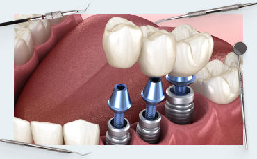
Custom abutments, designed through casting or milling for specific cases, emerged as a solution. With single implantations, these abutments nearly eliminate cement contact with soft tissues. They have also proven effective for multiple defects. For instance, the image below illustrates two implants placed at varying heights. The platform of the left implant is ideally positioned for a stock abutment and cement retention, whereas the right implant, being deeper, necessitates a custom abutment or screw retention.

Different levels of implant placement: on the right – the optimal fit is equally suitable for both screw and cement retention on a stock abutment; on the left – you need a custom abutment or a stock one for screw retention
In this case, it was decided to make a custom abutment for the right implant, and use a stock abutment for the left one.

Stock and custom abutments
Initially, custom abutments were cast, which was not only challenging but also costly. However, with the advent of CNC technology, it became feasible to mill individual abutments in any desired configuration, using materials such as titanium and zirconium dioxide.

Milling options for creating custom abutments
This advancement enabled the creation of restorations that perfectly align with the patient’s gum contours. Additionally, the abutment could be color-matched to the tooth enamel, ensuring that the gray titanium did not create an unsightly appearance at the gum line.

Restoration on a custom abutment made of zirconium dioxide with a titanium base for cement retention of the crown
In the case presented, the patient had chronic sinusitis, necessitating the angled placement of one of the implants to circumvent the maxillary sinus.

The patient has a history of chronic sinusitis – sinus lift is impossible, the second implant is installed at an angle to circumvent the maxillary sinus
The image shows impression transfers, and it is evident that selecting a stock angled abutment would be challenging. Consequently, the fabrication of a custom abutment was deemed necessary, as shown in the subsequent image.

Custom abutment for an implant installed in the tubercle of the upper jaw, 2014
The metal-ceramic restoration proved to be successful, as evidenced by the photograph taken a decade later.

Successful restoration supported by custom abutments – on the left, a custom abutment made on a CNC milling machine
The development of technology and digital dentistry has enabled many clinics to establish their own milling centers, granting significant freedom in the fabrication of bridges, abutments, and other complex elements. Notably, the integration of a titanium base with a zirconium individual abutment for aesthetic zones was particularly intriguing. However, the primary advantage of CAD/CAM technologies lies in the rapid development and production of prostheses. This efficiency has made the same-day installation of implants and prostheses a standard practice not only in large clinics but also in sophisticated private practices.
Yet, even custom abutments have not overcome the principal drawback of cemented restorations—beyond the issue of cement residues—the challenge of painlessly removing and reinstalling the prosthesis.
The alternative is screw-retained prostheses. However, for bridges and particularly for full-arch restorations, the conventional method suitable for single restorations is inadequate. Typically, this involves attaching a crown with a screw-access hole to a stock or slightly modified abutment and then securing the assembly into the implant. As discussed in the previous article, a single restoration could take an hour to install if it did not fit properly, adhering to adjacent teeth or presenting a tight implant/abutment interface that prevented proper seating. This difficulty is magnified in bridge restorations, where the alignment of three or more abutments must be coordinated.
Consequently, manufacturers have sought methods to adapt bridges for screw retention. One of the earliest solutions was introduced by Nobel for its NobelReplace implants, characterized by a deep interface lacking cones but featuring a triangular anti-rotation element at the top. The company suggested fabricating complex prostheses on castable abutments and modifying them for screw retention by shaping the interface to be slightly conical, allowing for a mere 2-3 mm of insertion into the implant.
 And A Castable Abutment With A Tapered Shortened Screw-Retained Interface For The Same Implants")
Standard interface of NobelReplace implants (left) and a castable abutment with a tapered shortened screw-retained interface for the same implants
Initially, such approaches were met with skepticism, but over time, experts acknowledged the efficacy of the design, and many restorations continue to function well to this day.
The image below depicts another restoration utilizing castable abutments designed for screw retention. In the early 2000s, planar interfaces were predominantly employed. The subsequent introduction of conical interfaces with anti-rotation elements compounded the challenge of simultaneously seating multiple abutments.

Successful screw-retained restoration on castable precious metal abutments
Conical interfaces have been incorporated alongside the existing planar interfaces. While some designs with complex anti-rotation elements have become obsolete, others remain in use.

Various implant/abutment interfaces that appeared on the market at the beginning of the 21st century
A straightforward method to modify such an interface for screw retention involves removing the hexagons and other anti-rotation features from the castable abutments. This simplification facilitates a passive fit. The risk of abutment rotation is mitigated by the bridge’s design, which is anchored by multiple implants and the interdependent stability of the prosthesis.

Conical abutment interface with hexagons removed

Successful screw-retained restoration on custom abutments with a tapered interface
Things to consider when installing multiple crowns on implants
Despite the sophistication of screw retention at the implant level on conical interfaces, they present a significant limitation. This stems from the physical principle of the Morse taper, which is the basis for the development of conical interfaces. The taper connection provides a very tight and secure fit, even in the absence of a screw. Consequently, during the fitting stage, it may not be possible to easily detach the abutment from the implant or to ensure that the finished prosthesis occupies the exact position as during the trial fitting. Such issues are not encountered with single restorations. However, installing multiple restorations such that all abutments are simultaneously immersed in the implants without causing distortion or jamming is exceedingly challenging.

Conical implant/abutment connections based on Morse taper
Achieving a passive fit for the prosthesis is crucial for long-term success. A passive fit prevents distortions and uneven loading on the screws and implant collars, thereby minimizing the risk of loosening, screw fracture, or implant cracking at the interface. Passive seating is highly valued by dental technicians and dentists, although objectively assessing the success of a passive fit can be difficult. The Sheffield test is a common method for evaluating passive fit, and a successful outcome is ideal. Nevertheless, we operate in a realm of inherent inaccuracies and acceptable errors. Each step, from impression taking to prosthesis fabrication, introduces slight deviations. Our aim is to achieve the utmost precision, where the restoration fits seamlessly without internal stress, and any gaps between components are only discernible under magnification.
For a prosthesis supported by two implants, attaining a satisfactory fit on conical interfaces is relatively straightforward. With three implants, the task becomes considerably more complex. It is nearly impossible to achieve simultaneous fitting for four or more implants. While such feats are achievable, they require exceptional expertise.
Another issue with screw retention at the implant level is the variability in cone angles among different manufacturers. For instance, within the Straumann brand, the Tissue Level implant series features a cone angle of 8°, while the Bone Level series has a cone angle of 15°, as illustrated below.

Different cone angles in Straumann implants: Tissue Level and Bone Level
When designing prostheses, it is essential to acknowledge that achieving perfectly parallel implant placement is impractical. Even with the use of a custom-made surgical guide, deviations between implants in both the sagittal and axial planes are inevitable. Consequently, fabricating a prosthesis that accommodates significant variances in implant alignment presents a considerable challenge.
Returning to the topic of conical angles, even in the absence of substantial deviations between implants along the longitudinal axis of the dentition, there are limits to the acceptable discrepancy between the axes of the implants. For a cone angle of 8°, the maximum discrepancy is 16° and for a cone angle of 15°, it should not exceed 30°, as depicted in the illustration below.

Maximum discrepancy between implants for tapered interface 15°
This limitation was significantly mitigated with the introduction of angled multi-unit abutments, which we will explore further later on.
Despite such constraints, there are instances of successful screw retention at the implant level. For example, consider the case illustrated in the photo below.

Screw-retained restoration at the implant level supported by four implants
This limitation was significantly mitigated with the introduction of angled multi-unit abutments, which we will explore further later on.
Despite such constraints, there are instances of successful screw retention at the implant level. For example, consider the case illustrated in the photo below.
The structure in question is extensive, supported by four Tissue Level implants. All the implants were installed in parallel, and a reasonably good passive fit was achieved, considering the relatively short conical sections of the abutments.
It’s important to note that achieving a passive fit for extended cement-retained restorations is also challenging. However, this issue is addressed by the substantial gaps where the prepared abutments meet the prosthesis. In the absence of cement, the prosthesis essentially dangles from the abutments, and it is standard practice for the 200-micron gaps to be filled with a layer of cement. The cement’s strength is sufficient for such restorations to endure for decades without issues.
Yet, an optimal solution for screw retention of complex prostheses supported by three or more implants involves multi-unit abutments. The primary distinction here is the dual retention and the addition of several components, including at least a second screw. Initially, the multi-unit abutment is inserted into the implant and remains in place for the lifespan of the restoration. The prosthesis itself is then secured with a screw to the abutment, which boasts a user-friendly interface. As such, multi-unit restorations are referred to as screw-retained at the abutment level, greatly simplifying the process for both dentists and dental technicians.
Let’s delve into the origins and development of multi-unit abutments. In the 1990s, Straumann introduced the SynOcta 1.5 abutment series. It’s worth mentioning that Straumann employed highly skilled engineers, many of whom had backgrounds in the watch industry and were experts in precision mechanics. These universal abutments were compatible with Tissue Level implants and enabled the attachment of both single crowns and multiple-defect restorations.

Universal abutment SynOcta 1.5 for Tissue Level implants

Principle of using screw retention with SynOcta 1.5 abutments
The SynOcta 1.5 abutment featured an integrated screw to fasten the abutment within the implant, as well as threading for a secondary screw that secures the crown or bridge. Indeed, this design is the precursor to contemporary multi-unit abutments.

Interface of multi-unit abutment predecessors on a jaw model
Accessories, such as sleeves, were available for these abutments. They were offered in two varieties: one made of completely incinerable, ashless plastic, and another with a metal base composed of precious metals.


Accessories for manufacturing of castable structures for SynOcta 1.5 abutments
These sleeves were utilized to fabricate cast frames for intricate prosthetic structures. The process was well-conceived, enabling the production of complex forms with superior aesthetic outcomes. However, it remained a challenging, labor-intensive, and costly endeavor, as designs of average complexity necessitated up to 5 grams of gold, in addition to a significant amount of highly skilled and precise workmanship. Despite these challenges, such restorations are durable and continue to be used effectively today.

Bridge on a cast frame without significant signs of wear after 10 years of use
In 2000, Nobel Biocare launched its system for screw-retained prostheses, known as the multi-unit system. This term has since been applied to all abutments that share a similar connection logic, much in the same way that the brand name Xerox became synonymous with all photocopying machines.

The first multi-unit abutment by Nobel Biocare introduced in 2000
Essentially, this represented an effort to introduce an additional interface at the abutment level for practical application. The interface of the initial multi-unit abutments bore a resemblance to the flat hexagon of Brånemark implants, yet it featured a slight taper.

External hex – one of the first implant/abutment interfaces
Multi-unit abutments have resolved the primary challenge associated with extended restorations by ensuring a good passive fit for complex prostheses supported by 6, 8, or more implants. The short conical tip of the multi-unit abutment, measuring 2-3.5 mm in height, has emerged as a universal solution for the reliable retention of prostheses. The difficulties associated with prosthesis installation have been significantly reduced.
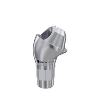
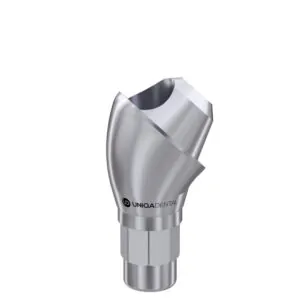
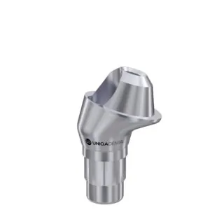
Subsequently, angled multi-unit abutments were introduced to the market, designed to compensate for substantial angular deviations between implants.

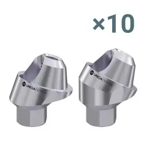
Example of angled multi-unit abutments


For example, angled multi-units by Uniqa Dental can compensate for angles up to 70° (17° modification). and up to 100° (30° modification).

Angled abutments and maximum compensation angle for non-parallel placement of implants
The introduction of angled multi-unit abutments provided a significant boost, initially to the prosthetics of full-arch restorations, and subsequently to the retention of prostheses within a single quadrant. This is particularly relevant when, for medical reasons, one or more implants must be placed at an angle to the occlusal line.
Astra Tech also contributed an innovative solution to the multi-unit market. Instead of creating separate angled abutments, they developed various interface options between the abutment and the prosthesis, as depicted in the illustration below.
")
How compensation of deviation angles is implemented in the Uni Abutment system (Astra Tech)
This technical solution also makes it possible to compensate for significant angles of deviation of implants from each other.
What to consider when installing multiple crowns on implants?
The primary challenge with multiple restorations is the risk of jamming and misalignment during the installation process. Despite the utilization of surgical templates, it is unfeasible to place all implants with absolute precision as per the 3D model. Screw-fixed restorations at the implant level are prone to complications, particularly when installing a prosthesis supported by more than three implants, due to the deep implant/abutment interface and the lengthy tapered portion of the abutment. Simplifying and shortening the abutment interface, as done in earlier solutions, addresses this issue but compromises the connection’s strength. Consequently, the screw, which operates under tension and bending, bears the primary load. Given that the screw’s thickness is just over a millimeter, the likelihood of breakage escalates. The multi-unit screw retention system is the only comprehensive resolution to this predicament.
Indeed, the inventors of multi-unit abutments have elevated screw retention to the abutment level. They have inverted the retention cone, which was initially oriented into the implant’s depth, to now extend into the prosthesis’s depth. This innovation has significantly streamlined the tasks of dental technicians and dentists.

Interface direction for screw retention at abutment level
Adopting this method, jaw scanning (digital impression-taking) is conducted at the abutment level rather than the implant level, resulting in high accuracy. Even if some inaccuracies arise during prosthesis manufacturing, they can be readily adjusted during fitting. Screw retention on multi-units is generally accommodating of minor flaws because the multi-unit abutment/prosthesis interface is:
- Short
- Angled, with its apex pointing towards the prosthesis, facilitating easy insertion into the prosthesis without the risk of distortion or jamming.
Moreover, from a biological standpoint, prosthesis retention at the abutment level is advantageous. The multi-unit abutment is placed once, around which a gingival cuff forms, maximizing the attachment of collagen fibers to the surface. As discussed in our series on soft tissue integration, the gingival attachment near implants is not as robust or reliable as that around a natural tooth. Frequent removal and reinstallation of the abutment can significantly degrade the connective tissue attachment, leaving only a delicate epithelial attachment.
Additionally, a one-time installation of an abutment with a tapered interface substantially reduces the risk of the abutment unwinding or loosening. The screw connecting the prosthesis to the multi-unit abutment may occasionally loosen, which is easily remedied, but the implant/abutment connection remains secure.
Statistics indicate that implant fractures most commonly occur:
- When thin implants (less than 4.8 mm) are placed in the masticatory area with a single crown.
- When a bridge is affixed at the implant level, often due to the prosthesis not seating smoothly, resulting in localized overstress on one of the implants. We will explore one such clinical case at the conclusion of the article.
Examining the Choice of Retention Type from a Practical Perspective
The study presented herein is not a meta-analysis and features a relatively modest sample size. However, the objectives of the research were highly specific, clearly articulated, and of practical significance.
The research involved volunteers, with specialists placing two implants in various regions, typically in the masticatory zone, on both the right and left sides. A number of restorations were crafted, each with inherent inaccuracies, specifically:
- Conditionally good restorations with excellent passive fit
- Restorations with not very good passive fit
- Restorations with very poor passive fit
These were not merely restorations but rather elaborate frames composed of precious metals, equipped with integrated sensors capable of connecting to specialized equipment to measure local stress concentrations.

Custom built bridge frame with built-in data acquisition electrodes
It is worth paying tribute to the volunteers who consented to participate in this study. After all, they had to accommodate such a device in their mouths for a duration of six months. Throughout the six-month period, researchers consistently monitored the stress levels in the area surrounding the implants. The findings were as follows:
In every instance, local stress levels diminished over time, regardless of whether the initial fit was good or poor.

Results of mechanical stress measurements over time
It turned out to be quite simple to explain this phenomenon, here are the conclusions.
“Within the limitations of this randomized clinical trial characterized by an observation period of 6 months and only healthy subjects being enrolled, bone adaptation around statically and dynamically loaded implants occurred, causing a decrease in misfit strain evoked by non-passively fitting prostheses. For maintaining osseointegration of dental implants, passivity of fit of multiunit restorations seems not to be as critical as previously thought.”
And this is very good. After all, apart from the well-known Sheffield test, there are no definitive methods to assess the accuracy of fit or detect overstresses. The study indicates that even restorations with imperfect fits can endure for a considerable duration, and absent critical local loads, issues are unlikely to arise.
Indeed, countless restorations are performed daily, and not all exhibit perfect fits. Yet, instances of failure are relatively infrequent. The same principle applies to restorations implemented following the immediate implantation protocol with concurrent prosthesis placement. In such cases, the implant is likely to assume an optimal position more swiftly during osseointegration, achieving secondary stability.
Bone, being a living tissue unlike inert materials such as concrete, wood, or plastic, should not be strictly assessed through the lens of classical mechanics. It responds to loading by adapting, densifying appropriately, and has the capacity to both expand and resorb. Consequently, the implant may slightly shift, leading to a more even distribution of load.
The researchers also observed that there exists a threshold of load beyond which bone cannot adapt or compensate; exceeding this limit will invariably result in failure—be it of a screw, an implant, or the bone itself. Although bones do not fracture in the conventional sense, they may resorb at points of excessive pressure. However, the precise level of these critical loads could not be quantified.
Regrettably, other studies of comparable data quality and conclusiveness on this subject are scarce. This research provides insight into why, despite less-than-ideal prosthesis fitting accuracy, widespread complications do not occur, and it confirms the existence of a threshold beyond which mechanical failure or biological loss of the implant is inevitable.
Clinical Case Analysis: Implant Fracture
Let’s examine an interesting case where a breakdown indeed occurred. A bone deficiency was noted in the distal mandible within the third quadrant. A short 6 mm Tissue Level implant was placed distally. Medially, near the area of tooth 35, a ⌀4.0 mm Bone Level implant was installed.

X-ray of implants and installed restoration in the area of teeth 35-37
Ideally, the second implant should have been a Tissue Level type, but due to the unavailability of the required size on the day of surgery, and the lack of opportunity for a subsequent operation, an available implant that met the necessary parameters was utilized.
A screw-retained restoration was fabricated at the implant level. The procedure was completed successfully. One year later, the patient returned for a routine check-up. Everything was found to be satisfactory; cleaning was performed, radiographs were taken, and a comprehensive examination protocol was documented.

External view of the restoration a year after installation – preventive examination in 2022

X-ray of the restoration taken during a preventive examination in 2022
Although the patient’s condition was satisfactory one year post-procedure, in 2023, they reported gum swelling and mild pain near tooth 35. Despite these symptoms, the restoration itself was stable. However, radiographic imaging revealed a fracture at the neck of the implant in the vicinity of tooth 35.

X-ray in 2023 showing that the implant is broken
Logically, the failure may be attributed to the stress exerted by the bridge, which was not offset by the bone tissue over time. As previously discussed, the body’s compensatory capabilities have their limits, and exceeding them will inevitably lead to a breakdown. In this instance, the implant was the “weak link.” The radiographs indicated that, over the year, bone resorption around the implant was minimal, with bone tissue loss becoming apparent only in the 2023 image, in conjunction with the fractured implant neck.
Given that this was a case covered by warranty, the patient received a new, larger-diameter Tissue Level implant, see the picture below.

New implant instead of a broken one
Fortunately, multi-unit abutments are available for Tissue Level implants, allowing the new restoration to be installed at the abutment level.


Steps to create a new screw-retained restoration using multi-unit abutments
Conclusions that can be drawn from this clinical case:
- There is always an inherent risk in clinical procedures, and outcomes can be unpredictable.
- There are solutions and techniques that minimize risk and shift it to a ‘safer’ area. With new restorations, there is a risk that the screw holding the prosthesis would get loose or break. However, this pertains only to the external part of the restoration and does not impact the patient’s bone or soft tissues. Such issues can be rectified non-surgically.
Conclusions and practical recommendations
This article does not serve as an endorsement of multi-units, nor does it disparage screw retention at the implant level. We present an objective assessment, and in most scenarios, multi-units offer a superior blend of benefits and user-friendliness.
Indeed, there are circumstances where an alternative retention type is preferable. For instance, in the anterior region, particularly with central incisors, it may be more advantageous to fabricate custom zirconium dioxide abutments and opt for cement retention. The good news is that casting custom abutments is no longer necessary; they are typically milled. An example of such a solution is illustrated in the accompanying photo.


Restoration of anterior teeth using custom zirconia abutments
In this case, a custom abutment provides an ideal aesthetic result; there is no metal visible through the gum, and no screw shafts exit onto the front surface of the prosthesis.
A certain wary rejection of multi-unit abutments persists among some specialists because, initially, they were unreasonably expensive. Now, the situation has stabilized, and almost all manufacturers offer one or another type of multi-unit for their implants. Moreover, the concept of interface compatibility has emerged, allowing multi-units from one manufacturer to be used with implants from other manufacturers. This is particularly beneficial if a patient presents with an old restoration and requires the installation of one or more implants so that the new prosthesis can rest on both new and existing implants.
A separate article may be devoted to the specifics of choosing and working with multi-unit abutments. However, it is now recommended that every specialist be proficient in working with all types of retention and select a solution based on the patient’s clinical picture. For more information, see our article “Comparison of Implant Abutment Connection Types“.
General conclusions and recommendations can be formulated as follows:
- If there is an extended structure with cement retention, it is necessary to create large gaps where the abutments enter the prosthesis.
- Screw retention at the abutment level is much safer and easier to implement compared to screw retention at the implant level. It is important to understand the mechanics of the downward Morse taper and the simple upward cone.
- For an extended structure with screw retention, it is best to utilize multi-units. Most professionals are likely already familiar with the standard protocols for dentition restoration supported by 4 or 6 implants, such as All-on-4 and All-on-6.
We hope the material in this article was useful. Stay tuned for our next publication.


-
-
-
-
Hot
10 Х 17° and 30° Angled Multi-Unit Abutment D-Type Internal Hex Regular Platform
Original price was: $680.$578Current price is: $578. Buy Now