How the implant/abutment connection affects soft tissue integration and marginal bone loss
Contents
Which is better: external and internal hex, platform-switching Morse taper or other interfaces?
This is the fourth article in a series on soft tissue integration of the implant.
We continue our series on soft tissue integration of the implant. After exploring GBR with Membranes, diving into Autologous Bone Grafts, and understanding the nuances of Allogenic and Xenogeneic Transplants, we now turn to the fourth part, in which we will look at how different types of implant/abutment connections affect the formation of the gingival cuff and bone resorption around the implant. We will look in detail at the relationship between the stability of the abutment in the implant and the level of marginal bone loss, and how the micro gap between the implant and abutment affects the long-term survival of the implant.
How different implant/abutment interfaces behave under mechanical loading
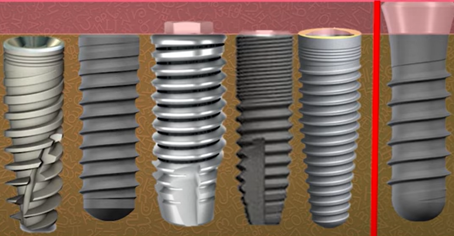
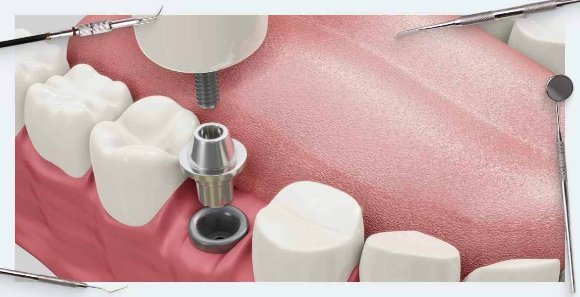
Let’s start with the types of implant/abutment connections. All implants can be divided into two main groups:
- Bone level implants (BL) – placed at the bone level
- Tissue level implants (TL) – placed at the gum level
The fundamental difference between them lies in where the connection between the implant and abutment will be in relation to the bone and the gingival cuff.
How the soft tissue connection is formed around TISSUE LEVEL implants has been discussed in detail in a previous article. This is a really good solution, but today we will look at how different types of interfaces in the BONE LEVEL class of implants affect the final result.
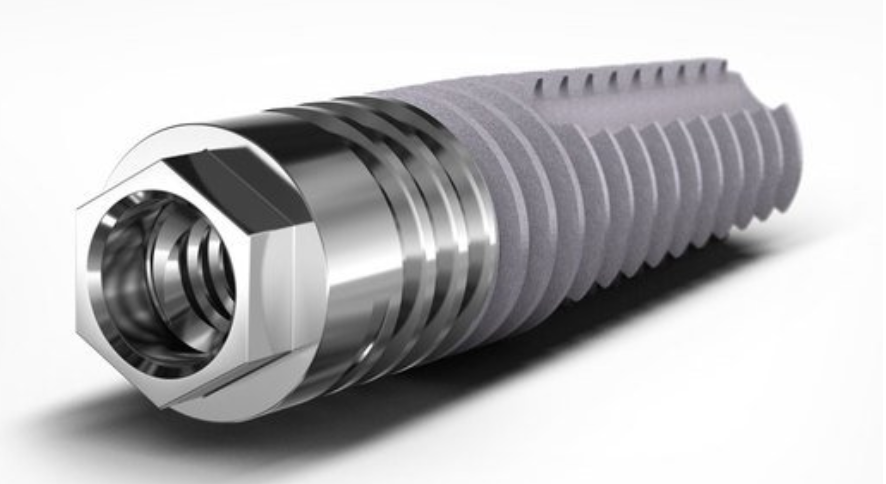
In this group of implants, we can clearly distinguish the external interface and internal connection.
The external interface is represented by one option with an external hex, which was actively used by Branemark himself.
Implants that have an external interface, in which the anti-rotational element is located above the implant platform, are still being produced and are unlikely to disappear from the market, as they have their advantages, such as greater mechanical strength for small implant diameters.
However, implants with internal interfaces dominate the market and are of particular interest to our article. There are many types of internal interfaces with triangular, hexagonal, and twelve-point anti-rotational elements, as well as various combinations of conical interfaces with platform switching and without.
For our study, it’s important to note that in this case, the implant/abutment interface is within the soft tissue.
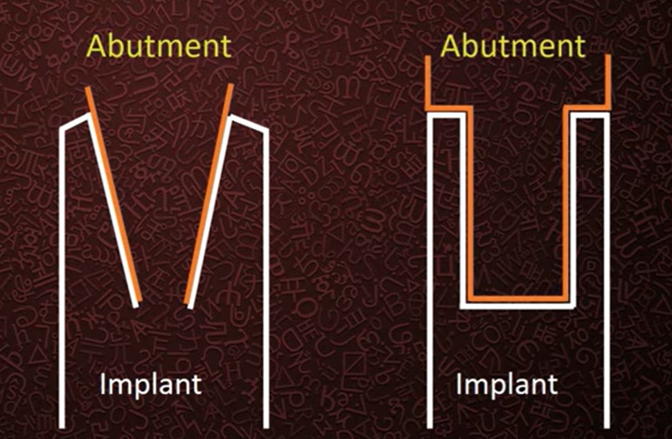
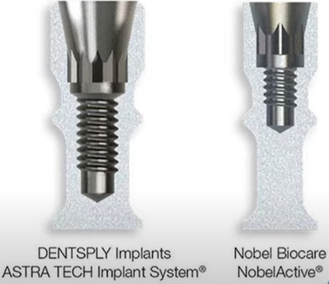
To simplify, we will categorize all internal interfaces into flat and conical types, see the illustration below.
Combinations of these types of connections are also common. The key difference between the flat and conical types is that in the case of a flat connection there must be a gap between the components otherwise one part cannot be inserted into the other, whereas a conical connection ideally joins without a gap. However, in reality, there is still a gap, but it can be much smaller compared to a flat connection.
These interfaces emerged almost simultaneously. Soon after the introduction of Branemark implants with an external flat connection to the market, implants of Professor Schreder’s design with a conical interface appeared. Both interfaces were developed with the involvement of skilled craftsmen and the connections proved to be very successful and reliable.
Let’s consider the differences between the interfaces from a purely mechanical point of view. Look at the illustration below, where the distribution of stresses under a lateral load applied at a 30° angle is shown in color.
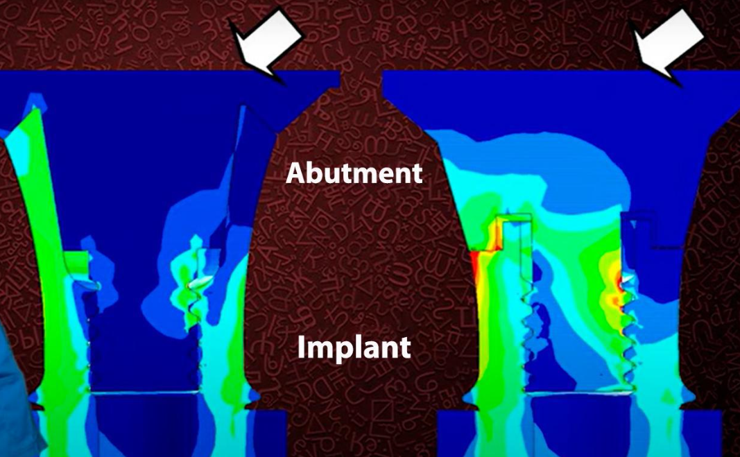
Visualization of load distribution and local overloading of flat and conical implant/abutment interfaces
The study was conducted on photoelastic models, and the illustrations clearly show that in the case of a conical connection stress points are much less and the load is distributed more evenly.
However, in the case of a flat connection peak overloads are visible in the area of the first and second threads on the screw. It’s worth noting that screws often break in these areas. We even have a separate article on how to safely remove a broken screw.
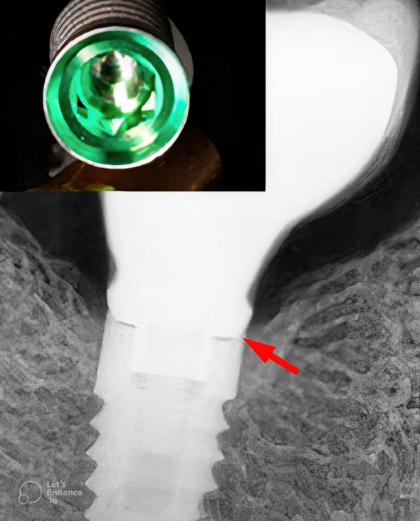
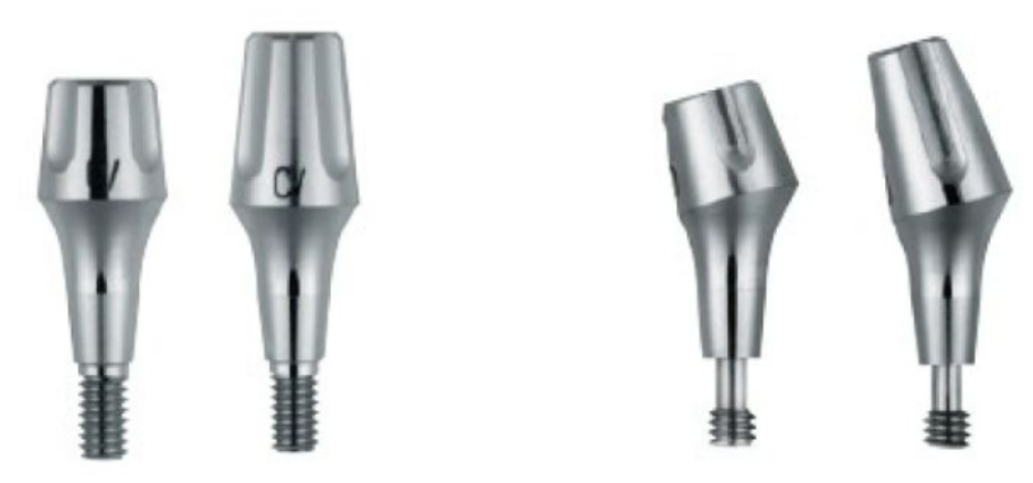
That’s why many manufacturers started incorporating conical connection elements into their interfaces. More often than not, we deal with combinations where there’s a classic hex anti-rotation element at the bottom of the connection and a conical part above it. These can be small bevels above the hex, as seen in the image below, or more intricate combinations as shown in the illustrations below.
There are many such combined interfaces, but there are also companies that exclusively use a conical connection (with a screw or without a screw) without additional anti-rotation interfaces. For example, monolithic abutments like Ankylos, which are a single component with a screw and do not have additional anti-rotation elements, see the illustration below.
There are even connections in which the abutment is held in place by the frictional properties of the cone and seat, without any screws or anti-rotation elements. Such a connection is also reliable enough to pass all tests and receive FDA approval.
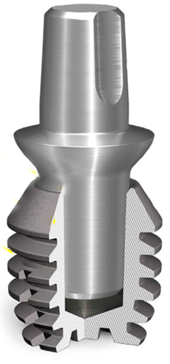
The cone within a cone is held in place solely by surface friction, without any screws or anti-rotation elements
It is important to understand that excellent mechanical properties are not the only thing to consider when choosing one type of interface over another. It is equally important to understand how the type of connection affects the level of bone resorption around the implant and other factors crucial for successful prosthetics.
Is a completely airtight implant-abutment connection possible?
To this day, there are heated debates among manufacturers about whose connection is more reliable in terms of airtightness. Some claim that only their cone is the true Morse taper and, therefore, completely airtight. Others assert that only they have such a high precision fit that the penetration of liquids and microbiota into the internal cavities of the implant is excluded.
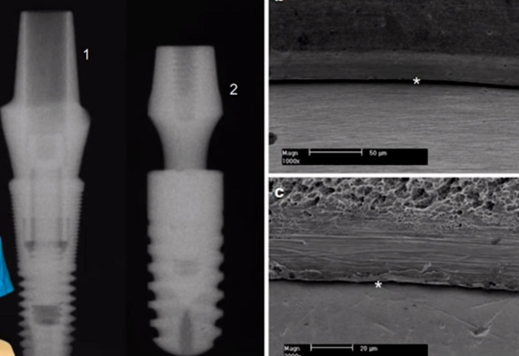
Let’s delve into what research results say about the airtightness of the implant/abutment connection for different types of connections. Below are microscope images of conical connections from two well-known and high-quality manufacturers, Astra and Ankylos.
In both cases, the gap between the parts is clearly visible, which means that tightness is out of the question. The comparison of gap sizes is not so significant, because even the smallest gap achieved today is considerably larger than the size of the microbes that inhabit the oral cavity.
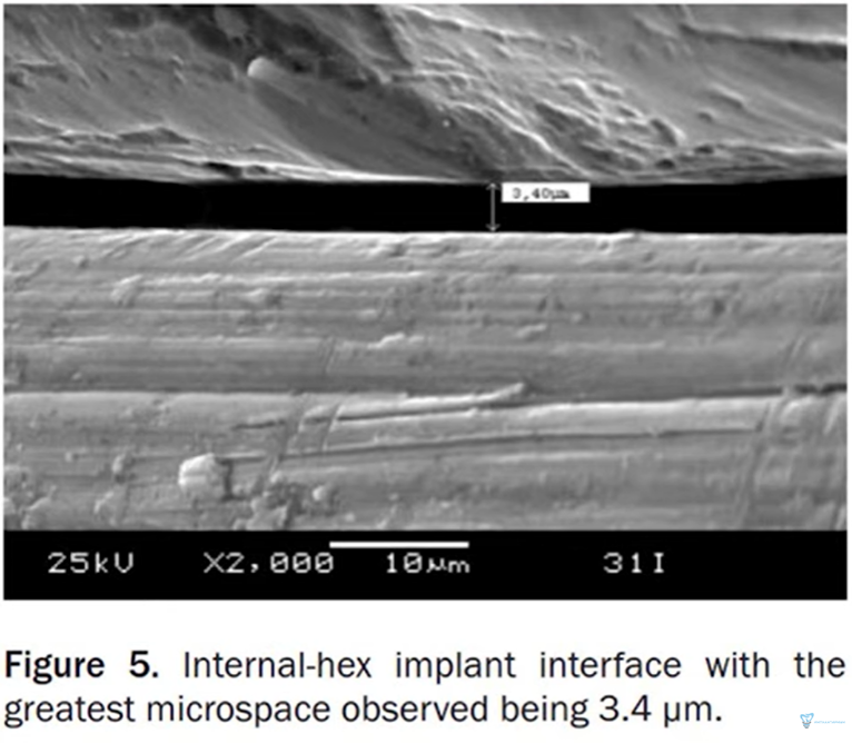
All the kinds of joints that have been viewed through optical and electron microscopes show that there is always a gap between the parts. The picture below shows a clearance of only 3.4 microns in the internal hexagonal planar connection, which is excellent because the average clearance in the implant/abutment connection is between 3 and 20 microns.
In general, it is not quite correct to specify a specific gap value because this value is variable, which can be clearly seen in the following pictures taken under high magnification.
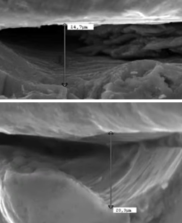
The gap between the implant and abutment with high magnification, you can see irregularities and caverns on the titanium surface
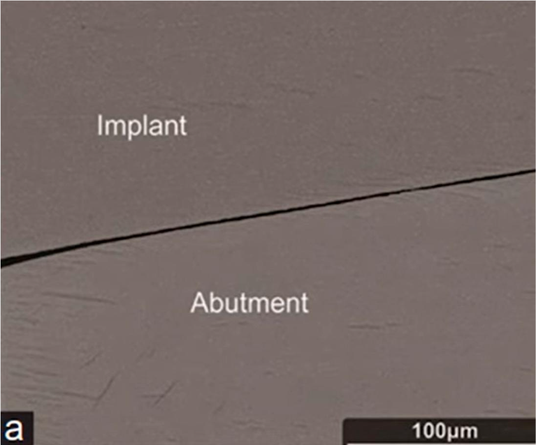
Returning to the comparison of the planar and tapered connection, the first image shows the tapered connection with a resolution of 100 microns and the junction of the surfaces looks smooth and thin.
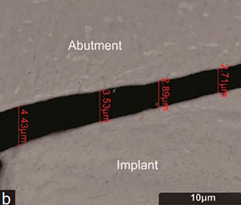
However, if you look with higher magnification, the gap will not look so perfect anymore.
The conical interface abutment fits very tightly and it is often difficult for the dentist to pull the conical interface abutment out of the implant. Even in areas of very tight contact and wedging, there is still a gap, see the following image.
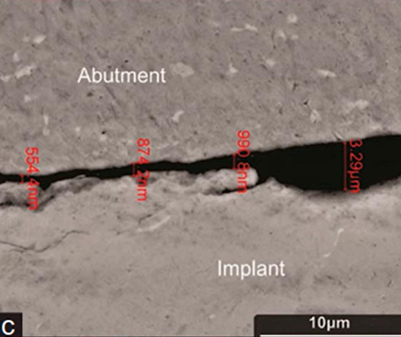
Micro-gap in areas of very tight contact (seizure) of the abutment in an implant with a conical interface
Please note that here the size of the gap is in tenths of a micron, so the scale in the image has switched to nanometers.
However, even a gap in the hundreds of nanometers is still larger than the size of bacteria that reside in the sulcus.
Let’s look at what research says about whether implant/abutment connections leak and if the microbiota penetrates through the gap. Such studies are conducted in vitro and various methodologies are used for this.
Most often, they take:
- A sterile implant from the packaging and a sterile abutment;
- Introduce a culture of bacteria or endotoxin inside the implant (depending on what the researchers want to find out);
- Install the abutment and fully tighten the screw according to the manufacturer’s recommendations;
- Place the implant with the abutment in a sterile test tube with distilled water or directly into a nutrient medium and check whether the bacteria inside are multiplying in the external environment.
The second method to test the integrity of the connection is as follows:
- Connect a sterile abutment and implant in a way that does not introduce any microorganisms inside;
- Place them in an environment with microorganisms for a certain period; and
- Rinse the sample, remove the abutment, and check if bacteria have penetrated inside the implant.
There is another testing method in which the implant/abutment connection is subjected to mechanical stress during the testing period to determine how micromobility affects the amount of microflora that penetrates through the connection.
Let’s delve into the results that the connection shows at rest. To do this, let’s refer to the study results from the University of San Paolo.
In their study, they used all kinds of compounds that exist and are used in dental practice.
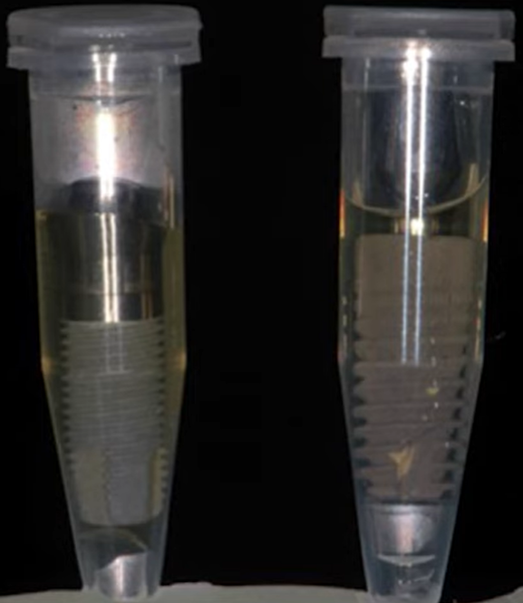
According to the study protocol, a bacterial material, namely Staphylococcus aureus, was placed inside the implant under sterile conditions. After that, the abutment was placed and the implant with the abutment was placed in a tube with sterile liquid, see illustration below.
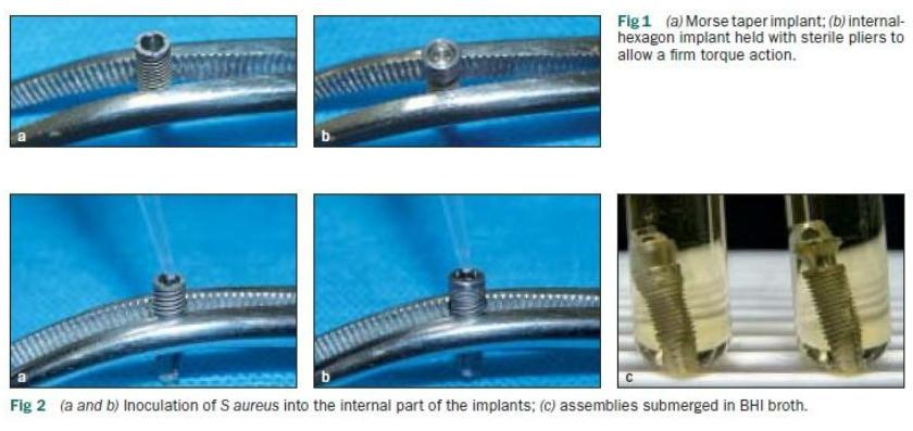
Sequence of introducing bacterial material into the implant to test the density of the implant/abutment connection
After some time, the fluid samples were placed in a nutrient medium and the scientists observed whether Staphylococcus aureus would grow there. If yes, then the implant/abutment connection could not be a sufficient obstacle.
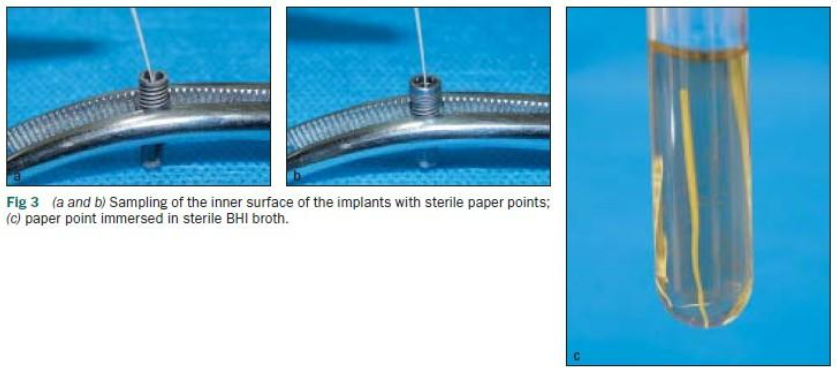
In the other group, they took a sterile implant and abutment, combined them and placed them in a “broth” with staphylococcus aureus. After some time, the abutment was removed and a thin paper rod was used to take a sample from inside the implant, put it in a nutrient medium and see if there would be Staphylococcus aureus there.
Naturally, at all stages and for all methods, there was a control group where implants and abutments were connected and disconnected in sterile conditions, and samples were also taken for culturing.
As a result, it was found that bacteria penetrated through the connection and successfully multiplied in all types of connections.
Other studies using different types of microorganisms or toxic proteins also showed that to date, there is no sufficiently reliable connection that would serve as a barrier to the oral cavity’s microbiota.
This is under ideal conditions without any load, which is not the case in real life because during chewing, the abutment is subjected to both vertical and lateral loads.
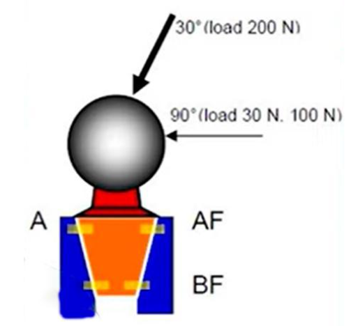
To understand what happens to the interface and clearances under load consider another Berlin Group study from 2013.
No bacterial components were used; only the effect of 30° and 90° loading on the gap size was studied. A special X-ray machine was used for control, which allowed the gap size to be determined with great accuracy.
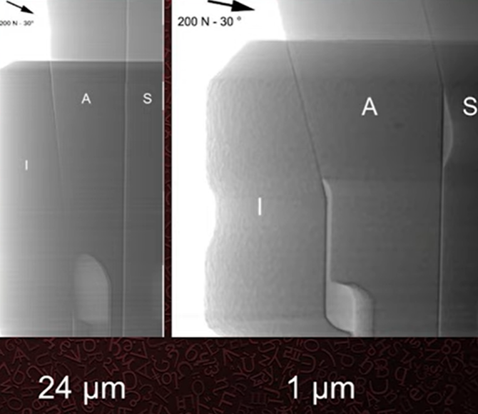
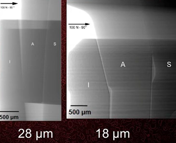
Two classical implants Ankylos and Straumann (Bone Level) were used for the study, in which a ball abutment was inserted and a clearly defined load of 200 N at an angle of 30° 100 N at an angle of 90° was applied.
At the same time as the load was applied, a series of images were taken to record the change in the gap between the implant and the abutment.
As a result, it was found that the clearance was smaller with a 30° angle of load than with a smaller load at an angle of 90°, see images below.
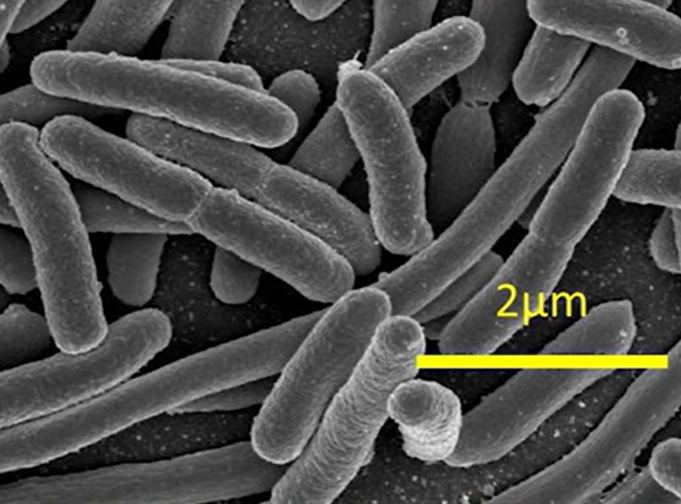
However, for the purposes of our article, it is important to note that these gaps do exist, and they are significantly larger than the size of microorganisms present in the oral cavity. For example, in the photo below, one of the largest bacteria, E. coli is approximately 2 microns in length.
However, the majority of the oral cavity microflora is much smaller. For example, take a look at two representatives of the microflora that actively proliferate in periodontal diseases and peri-implantitis.
Notice the size, and now recall one of the best values for cone joints where the gap ranged from 2.7 to 4.4 microns. Obviously, for these and similar microorganisms, such a gap is a wide-open gate.
That is why we are skeptical of the manufacturers’ enthusiastic statements about airtightness at a gap of 3 microns. To dispel all doubts and finally resolve the long-standing dispute of internal hex vs conical connection, here is another systematic review by Berlin researchers.
The high quality of this study is evidenced by how the questions and answers that the scientists intended to address in this research were formulated:
- Whether implant systems with a tapered implant/abutment connection provide a better seal than non-tapered systems under mechanical loading in vitro.
- Does the use of a tapered (Morse taper) implant/abutment connection result in less marginal bone level loss and higher implant survival compared to a non-cone connection system in vivo.
These are the conclusions of the researchers (in vitro):
- There is no connection that would ensure 100% sealing against bacterial contamination. However, there is evidence that conical implant/abutment connections outperform others in terms of sealing.
- Conical connection systems of implant/abutment are more resistant to abutment micromovement and gap enlargement under load. Internal and external hexagons behave less favorably in terms of abutment micromovement and microgap enlargement.
- The conical connection is more successful in resisting screw loosening compared to other systems.
- The conical connection exhibits high resistance to fatigue loads and maximum resistance to bending.
- The conical connection compensates for and distributes the load on the abutment and protects the screw from overload.
Conclusions (in vivo):
- Conical and non-conical connections are comparable in terms of implant success and survival.
- In most cases, conical connections appear to lead to less crestal bone loss.
At first glance, the conclusions may seem slightly contradictory because it appears that despite the mechanical superiority of the conical system, there is no significant difference between interface types in the long run.
Is there a correlation between the level of bacterial contamination and crestal bone resorption?
To answer this question, we will refer to a study by the Bernese group from 2011.
The material for the study consisted of Branemark implants that had been in the mouth for approximately 10 years, with an average of 9.5 years. All restorations were fixed and primarily performed in the upper jaw. The study included somatically healthy patients without signs of peri-implantitis or other oral cavity issues.
The researchers measured bacterial colonization at various points. The illustration below clearly shows a Branemark implant with an external hexagon, indicating all the points from which bacterial plaque was sampled.
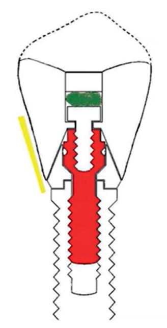
The points from which bacterial samples were taken were the sulcus, the crown screw head, and the abutment screw
First, they placed a sterile paper rod for 20 seconds in the sulcus (yellow area) and then performed a series of tests, including PCR tests.
Then they opened the shaft of the screw that connected the denture to the abutment and took a sample from there (green area).
Finally, the screw was carefully unscrewed and samples were taken from it for seeding (red screw in the illustration).
That is, there were three points for the study and as a result it was found that in all points there is a full spectrum of microbiota that generally occurs in the human oral cavity.
These are the conclusions drawn by the researchers:
There was practically no connection between microbes in different parts of the implant interface, suggesting significant movement along the composite plug and occlusal screw.
When comparing the flora taken from the abutment screw with the flora from the peri-implant sulcus, most species differed and were present in the sulcus in fewer quantities than on the screw. Nevertheless, a strong correlation in the quantity of bacteria in different parts of the interface was noted.
Although all implants in this study showed no clinical signs of peri-implantitis, the high colonization by numerous species associated with pathology was surprising.
These conclusions are also supported by another meta-study.
This meta-analysis demonstrated that bacteria can easily colonize the implant-abutment connection. From a clinical standpoint, the internal parts of the implant/abutment connection should always be considered contaminated, even under clinically healthy conditions.
In other words, pathogenic microorganisms are always present in everyone and everywhere, but this does not always lead to diseases. Therefore, there is no direct correlation between the level of bacterial contamination and marginal bone resorption.
What is the effect of the implant/abutment gap on marginal bone resorption and what is the effect of micro-mobility in the area of the implant/abutment connection on marginal bone resorption?
These two questions can be answered by the results of a study from 2001.
The study was conducted on dogs. Implants and abutments of the same design were taken and installed using a standardized protocol. However, in one group, the implants were welded to the abutments, ensuring complete immobility, while in other groups they were screwed in using the standard procedure allowing for some micromotion.
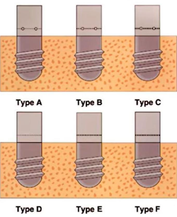
The research samples consisted of three welded abutments with different gaps and three screwed abutments with the same gap sizes
The second part of the study was to determine how the gap size affected marginal bone loss, so all the test specimens had different clearances.
For example, there were three welded samples with 10, 50, and 100 microns of clearance, and three screwed samples with the same clearances. To get these gaps, the researchers specially ground the samples to get the right amount of clearance.
Here are the results obtained in the histologic studies:
- Fixed (welded) samples showed minimal bone loss around the implant regardless of the gap size.
- Screwed (non-welded) samples exhibited significant bone loss irrespective of the microgap width.
This indicates that even with the most precise fit between implant components (≤10 microns), it is impossible to prevent bone loss. This is because screw fixation of the two parts cannot eliminate micromotion between the implant and the abutment.
Let’s summarize the results in al table:
| Key question | Answer |
| Whether a hermetic implant/abutment connection is possible | No |
| Is there a relationship between the level of bacterial contamination and marginal bone resorption? | Not direct |
| What is the effect of implant/abutment gap on marginal bone loss? | None |
| What is the effect of micro-mobility at the implant/abutment junction on marginal bone resorption? | Direct, the less mobility, the less bone loss |
The key conclusion we want to share is that rest and stability of the implant/abutment system ensure high-quality integration in both aspects: osseointegration and soft tissue integration. The difference between the interfaces is secondary, although it is worth noting that the conical connection, in most cases, provides better stability of the connection.
Therefore, a conical implant/abutment connection can prevent bone resorption by reducing mobility.
We hope the content of this article has been helpful to you. See you in the next article of the series, which will focus on subcrestal implant placement and integration specifics.

